
Related Manuals for eta AMS DIGITAL


Summary of Contents for eta AMS DIGITAL
- Page 1 AMS DIGITAL - AMSA DIGITAL AMS DIGITAL AMSA DIGITAL SOLENOID DRIVEN METERING PUMPS WITH DIAPHRAGM...
-
Page 2: General Safety Guidelines
This operating instructions contains safety information that if ignored can endanger life or result in serious injury. Read these instructions carefully before use and keep them for future reference. The original instruction is in Italian. All non-Italian instructions are translations of the original instruction. Information and specifications on this manual could be uncorrect or could have printing errors. - Page 3 pURpOSE METERING pUMp IS INTENDED FOR ChEMICAL DOSING AND DRINkING WATER TREATMENT. OF USE AND SAFETY Do not use in explosive area (EX). Do not use with flammable chemicals. Do not use with radioactive chemicals. Use after a proper installation. Use the pump in accordance with the data and specifications printed on the label.
-
Page 4: Environmental Safety
ENVIRONMENTAL Work area Always keep the pump area clean to avoid and/or discover emissions. SAFETY Recycling guidelines EWC code: 16 02 14 Always recycle according to these guidelines: 1. If the unit or parts are accepted by an authorized recycling company, then follow local recycling laws and regulations. - Page 5 TRANSpORTATION A not suitable transportation or storage can cause damages. AND STORAGE Use origianal box to pack the pump. Observe storage conditions also for transportation. Although packed, always protect the unit against humidity and the action of chemicals. Before return the dosing pump to the manufacturer Repair service, drain the chemical ⎘...
-
Page 6: Alternating Current
1. Introduction 1.1 Introduction Metering Pumps “AMS DIGITAL” Series are the ideal solution for low / middle dosing of chemicals. All control and setup parameters are available through a digital keyboard and they are displayed on a LCD backlit display. - Page 7 2. Unpacking Included into package: Dibbles ø6 Self tapping screws 4,5 x 40 Delayed fuse 5 X 20 Level probe with axial foot filter (PVDF) Injection valve Delivery pipe (PVDF) Suction pipe (transparent PVC) Venting pipe (transparent PVC) m 2,5 Signal cable for “Stand-by”...
-
Page 8: Pump's Description
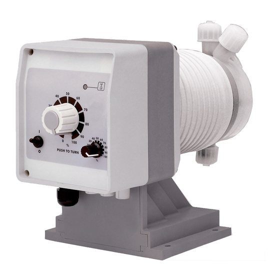
3. pump’s description Manual stroke length adjustment RED THREADING ⎘ Max cc/stroke ( Construction Materials and Technical info) are referred to cc/stroke with stroke length knob on 100%. The stroke length knob adjusts the pump capacity. Press and rotate the knob when the pump is powered. Dosing accuracy is guarantee within an adjustment range from 30% to 100%. -
Page 9: Before To Install Warnings
4. Before to Install warnings Pump’s installation and operativity is made in 4 main steps: Pump’s installation Hydraulic Installation (hoses, level probe, injection valve) Electrical Installation (main power connection, priming) Programming the pump. Before to start, please read carefully the following safety information. Protective clothes Wear always protective clothes as masks, gloves, safety glasses and further security devices during ALL installation procedure and while... -
Page 10: Installation Draw
5. Installation draw Pump must be installed in a stable support (for example a table) at a maximum height (from tank’s bottom) of 1,5 meters. 1 - Dosing Pump 2 - Suction Hose 3 - Delivery Hose 4 - Injection Valve 5 - Air discharge 6 - Level Probe 7 - Foot Filter... -
Page 11: Hydraulic Installation
6. hydraulic installation Hydraulic connections are: Suction Hose with level probe and foot filter Delivery Hose with injection valve Venting hose Suction hose. Completely unscrew tightening nut from pump’s head and remove assembling components: tightening nut, holding ring and pipe holder. Assembly as shown in fig. - Page 12 Assembling foot filter with level probe. Level probe must be assembled with foot filter using the provided kit. Foot valve is made to be installed into tank’s bottom without sediments priming problem. STEP 5 STEP 4 INSERT RING AS SHOWN STEP 3 INSERT PROBE WITH N.O.
-
Page 13: Injection Valve
Injection Valve. Injection valve must be installed on plant from water’s input. Injection valve will open at pressure greater than 0,3bar. Venting hose. Insert one side of venting hose into discharge connector as shown in fig (C). Insert other side of venting hose into product’s tank. During priming procedure product exceeding will flow into tank. - Page 14 6. hydraulic Installation 7. Self-Venting pump head installation Self-venting pump head must be used when using chemicals that produce gas (i.e. hydrogen peroxide, ammonium, sodium hypoclorite at particular conditions). Refer to fig. 4-5 for delivery and venting hose. Hoses assembling procedures are the same described before. Fig.
-
Page 15: Electrical Installation
8. Electrical Installation All electrical connections must be performed by AUThORIZED AND QUALIFIED personnel only. Before to proceed, please, verify the following steps: - verify that pump’s label values are compatible with main power supply. - pump must be connected to a plant with a differential switch (0,03A sensitivity) if there isn’t a good ground. - Page 16 Once verified previous steps proceed as follows: - check that “BNC” of level probe has been connected as described in “Hydraulic Installation” chapter. - connect “BNC” and external signal to pump’s “INPUT” connectors. Ingresso RS485 Level Probe Input pH electrode input Power Supply Redox electrode input Input...
- Page 17 9.2 LEVEL ALARM All “AMS Digital” series pump are provided with a liquid level alarm to indicate if product tank is empty. The level probe is connected to the right BNC plug on pump’s bottom panel. The level probe is made of a N.O. reed contact (10VA, 1A max, 230Vac max) closed by a floating magnet housed in a (PP) plastic box.
-
Page 18: Basic Settings
10. Basic settings 10.1 “START/STOp” - pRIMING BUTTON This allows to start or stop pump programmed operations as well as to prime the pump. Pressing this button, while the pump is working, will display OFF (flashing). Continuing to press the button “START-STOp” while OFF is showing, will change the display into MAN, and the pump will deliver 80 strokes. - Page 19 11. AMS EXT / RS485 model AMS “EXT/RS485 “ MODEL On demand the pump can be supplied with serial interface, installed in the pump electronic circuit. Specific requests are accepted when ordering. RS485 transmission provides serial connection and requires two wires and screen. Using a 120 Ohm impedance-line, perfectly balanced, it is possible to connect up to 1 Km distance without intermediate am- plifiers.
- Page 20 13. AMS ph model AMS PH LCD backlit display Storke Lenght Knob Turn the pump on or off and exit from setup menu (without saving parameters) Scroll and increase digit Enter / exit from setup menu (saving parameters) The “AMS PH” pump is equipped with a keyboard.To avoid any misunderstanding during next chapters all keys will be described as shown on this legend: ON/OFF “Up”...
-
Page 21: Probe Calibration
7.30pH fig.4 The display shows that pump does not work at 00% if pH is 7.30. Make sure that arrow is on “7.30 pH” to change this value, then use “UP” and “DOWN” keys to enter a new value. Use “RIGHT” key to move on next value. Once on “00%”, change it with “UP”... -
Page 22: Special Functions
DELAY In main menu choose “PARAM” (fig.2) and press “E” key. Display shows: DEL.: ->00 0 0 0 0 fig.9 The -> arrow is on “DEL”. This value is pump’s waiting time after any start up procedure: pump will wait set time before start dosing every time it is powered on. -
Page 23: Troubleshooting
14. Troubleshooting problem possible Cause Pump isn’t powered. Connect it to main supply. Pump’s protection fuse is broken. Replace it. See page 24 for pump doesn’t turn on. replacement procedure. Pump’s main board is broken. Replace it. See page 24 for replacement procedure. -
Page 24: Fuse And Main Board Replacement
15. Fuse and main board replacement Fuse or main board replacement is allowed to qualified personnel only. Before to operate disconnect the pump from main power and all hydraulic connections. For fuse replacement is necessary to use a 3x16 and 3x15 screwdriver and a new fuse (same model of old one). For main board replacement is necessary to use a 3x16 and 3x15 screwdriver and a new main board (same model of old one). -
Page 25: Main Board
16. Main Board Mod. “AMS Ext/ 485” Transformer FUSE Solenoid power supply Level + Signals for “AMS Ext/485” Signal + model only... -
Page 26: A Appendix. Maintenance
A Appendix. Maintenance. Maintenance In order to ensure the requirements of potable drinking water treated and the schedule maintenance of the improvements as declared by the manufacturer, this equipment must be checked at least once a month. OpERATOR pROTECTION Use safety equipment according to the company regulations. Use this safety equipment within the work area during installation, service and when handling chemicals: •... - Page 27 f the pump performance does not satisfy your process requirements, and the process requirements have not changed, then perform these steps: 1. Disassemble the pump. 2. Inspect it. 3. Replace worn parts. This procedure ShOULD BE CARRIED OUT BY AUThORIZED AND QUALIFIED Shutdown procedure pERSONNEL...
-
Page 28: B Appendix. Construction Materials And Technical Info
B Appendix. Construction Materials and Technical info Features Power Supply 230 VAC (180-270 VAC) - 50/60 Hz 115 VAC (90-135 VAC) - 50/60 Hz 24 VAC (20-32 VAC) - 50/60 Hz 12 VDC (10-16 VDC) Environment temperature ......10 ÷ 45°C (32 ÷ 113°F) Chemical temperature ........ -
Page 29: C Appendix. Delivery Curves
C Appendix. Delivery Curves 2505: 1510: l/h 05 bar 25 l/h 10 bar 15 Pump head mod. L Pump head mod. M 0720: 0340: l/h 20 bar 7 l/h 40 bar 3 Pump head mod. N Pump head mod. S 0260: l/h 60 bar 2 Pump head mod. -
Page 30: C Appendix. Delivery Curves For Self-Purge Pump Head
C Appendix. Delivery Curves for self-purge pump head 253,2: l/h 25 bar 3,2 1506: l/h 6 bar 15 Pump head mod. LA Pump head mod. MA 0713: l/h 13 bar 7 1010: l/h 10 bar 10 Pump head mod. NA Pump head mod. -
Page 31: D Appendix. Dimensions
D Appendix. Dimensions 87.00 152.60 154.80 127.00 265.70 283.20 Progettato da Controllato da Modificato da, Massimo_F 87.00 152.60 127.00 154.80 278.20 295.70 Progettato da Controllato da Modificato da, il Data Massimo_F 27/01/2010 Materiale: Edizione Dimensionale-CMS_Cp_S-T... -
Page 32: E Appendix. Chemical Compatibility Table
E Appendix. Chemical Compatibility Table Solenoid driven metering pumps are widely used to dose chemical fluids and it is important that the most suitable material in contact with fluid is selected for each application. This compatibility table serves as a useful help in this respect. All the informations in this list are verified periodically and believed to be correct on the date of issuance. -
Page 33: F Appendix. Hoses Resistance Table
F Appendix. hoses resistance table Hose features are very important for a reliable dosage. Every pump’s model is made to work in the best way using selected hoses according to pump’s capacity / model. Information reported here are intended for standard use only. For extended information ask to hose’s manufacturer. - Page 34 G Appendix. Installation draw for AMS ph/Rh...
- Page 35 h Appendix. Exploded view Edizione Foglio Esploso_CMSMF_CP_T...
- Page 36 I Appendix. Index GENERAL SAFETY GUIDELINES ..............2 PURPOSE OF USE AND SAFETY ..............3 LEGEND ....................3 ENVIRONMENTAL SAFETY .................4 LABEL .......................4 SPARE PARTS ....................4 TRANSPORTATION AND STORAGE ..............5 1. Introduction ..................6 2. Unpacking .....................7 3. Pump’s description ................8 4. Before to Install warnings ..............9 5.
- Page 37 ETA Ekipman Teknoloji Ar. Sis. San. Tic. Ltd. Şti. www.etaekipman.com info@etaekipman.com Tel:0 216 540 99 64 Fax:0 216 540 99 68...
Need help?
Do you have a question about the AMS DIGITAL and is the answer not in the manual?
Questions and answers