Table of Contents
Advertisement
Quick Links
K PLUS - K CL PLUS - K CO PLUS
Self-venting version: KA PLUS
6
5
4
D
C
6
5
4
D
B
C
A
Progettato da:
Massimo_F
6
5
4
B
6
5
D
A
C
Progettato da:
Massimo_F
6
5
4
B
A
6
5
SOLENOID DRIVEN METERING PUMPS
WITH DIAPHRAGM
3
2
3
2
K CL PLUS
Controllato da:
Data:
Peso Lordo:
Toll. Gen.
Massimo_F
31/05/2013
±0.05
Materiale:
A3 EMEC_Verticale
3
2
K CO PLUS
4
3
Controllato da:
Data:
Peso Lordo:
Peso Netto:
Toll. Gen.
Massimo_F
31/05/2013
±0.05
Materiale:
Edizione Foglio
A3 EMEC_Verticale
00
3
2
K PLUS
Progettato da
Massimo_F
4
3
1
D
C
1
D
B
C
A
Peso Netto:
Edizione Foglio
/
00
1 1
1
B
2
1
A
/
1 1
1
Controllato da
Modificato da
Data
Toll. Gen.
16/11/2010
Materiale:
Edizione
A3emec
00
2
1
EN
D
C
B
A
0.05
Foglio
1 1
/
Advertisement
Table of Contents

Related Manuals for eta K CL PLUS Series


Summary of Contents for eta K CL PLUS Series
- Page 1 K PLUS - K CL PLUS - K CO PLUS Self-venting version: KA PLUS K CL PLUS Progettato da: Controllato da: Data: Peso Lordo: Peso Netto: Toll. Gen. Massimo_F Massimo_F 31/05/2013 ±0.05 Materiale: Edizione Foglio A3 EMEC_Verticale K CO PLUS Progettato da: Controllato da: Data:...
-
Page 2: General Safety Guidelines
This operating instructions contains safety information that if ignored can endanger life or result in serious injury. Read these instructions carefully before use and keep them for future reference. The original instruction is in Italian. All non-Italian instructions are translations of the original instruction. Information and specifications on this manual could be uncorrect or could have printing errors. -
Page 3: Purpose Of Use And Safety
PURPOSE OF USE METERING PUMP IS INTENDED FOR CHEMICAL DOSING. AND SAFETY Do not use in explosive area (EX). Do not use with flammable chemicals. Do not use with radioactive chemicals. Use after a proper installation. Use the pump in accordance with the data and specifications printed on the label. Do not modify or use in a manner inconsistent with the provisions of the operating manual. -
Page 4: Environmental Safety
ENVIRONMENTAL Work area SAFETY Always keep the pump area clean to avoid and/or discover emissions. Recycling guidelines EWC code: 16 02 14 Always recycle according to these guidelines: 1. If the unit or parts are accepted by an authorized recycling company, then follow local recycling laws and regulations. -
Page 5: Included Into Package
Transportation and A not suitable transportation or storage can cause damages. storage Use origianal box to pack the pump. Observe storage conditions also for transportation. Although packed, always protect the unit against humidity and the action of chemicals. Before return the dosing pump to the manufacturer Repair service, drain the chemical ⎘... -
Page 6: Description
DESCRIPTION K PLUS K PLUS is a constant or proportional dosing pump with level control for chemical feeding into water. In Constant dosing mode pump doses a constant quantity regularly as configured by the user. In Proportional dosing mode pump doses a quantity proportionally to an input signal, digital (voltage free contact) or current (mA). -
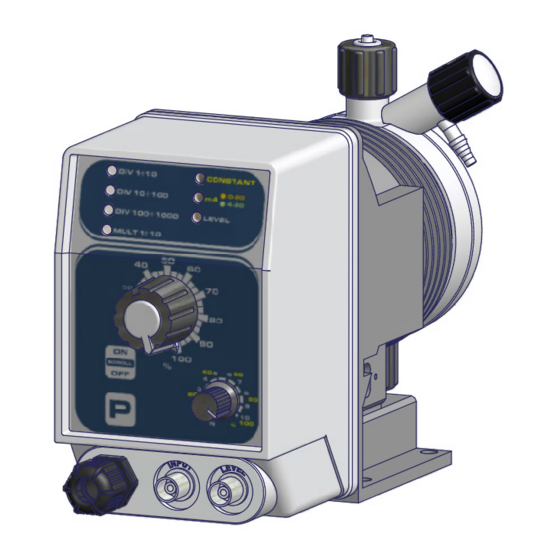
Page 7: Fig. 3. K Plus - Ka Plus
Fig. 3. K PLUS - KA PLUS Modificato da Progettato da Controllato da Data Toll. Gen. Massimo_F 0.05 16/11/2010 Materiale: Edizione Foglio A3emec... -
Page 8: Features
Features Power Supply Fuse 230 VAC (180-270 VAC) - 50/60 Hz 115 VAC (90-135 VAC) 500 mA - 50/60 Hz 24 VAC (20-32 VAC) - 50/60 Hz 12 VDC (10-16 VDC) Environment temperature ......10 ÷ 45°C (55 ÷ 113°F) - 50/60 Hz Chemical temperature ......0 ÷... -
Page 9: Manual Stroke Length Adjustment
Tab. 2. Capacity (compressed air model) CAPACITY Flow cc per stroke * Delivery pressure Suction Pump Modello hose K AC PLUS hose head (PVDF) cc/h 1018 0.16 6 x 8 6 x 8 * cc per stroke: referred to cc/stroke with stroke length knob on 100%. ⎘... -
Page 10: Installation
INSTALLATION How to install 5 steps to install and start-up the pump: metering pump Pump location Piping connections (hoses, level probe, injection valve) Wirings Pump priming Programming and start-up The operator must be aware of safety precautions to prevent physical injury. POWER SUPPLY DISCONNECTION User health and safety... -
Page 11: Fig. 4. Installation
Fig. 4. Installation 1 - Dosing Pump 2 - Suction Hose 3 - Delivery Hose 4 - Injection Valve 5 - Air discharge 6 - Level Probe 7 - Foot Filter 8 - Power Cable 9 - Stand-by/alarm (if any) Max 1,5 mt... -
Page 12: Piping Connections
PIPING CONNECTIONS Foot filter / Level Level probe is assembled with a foot filter that avoid sediments priming probles. probe Install level probe on the bottom of the tank. (included only in Connect BNC level probe to the pump BNC input. some models) Warning: If there is a mixer installed into tank, install a suction lance instead of level probe / foot filter. -
Page 13: Suction Hose Connection
Suction hose Suction piping should be as short as possible and installed in vertical position to connection avoid air bubbles suction. Completely unscrew tightening nut from pump’s head and remove assembling components: tightening nut, holding ring and pipe holder. Assembly as shown in fig. 5. Insert hose into pipe holder until it reaches the bottom. -
Page 14: Injection Valve
Injection valve Injection valve must be installed on plant from water’s input. Injection valve will open at pressure greater than 0,3 bar. On request 1, 2, 3, 4 or 5 bar injection valve are available. Venting hose Insert one side of venting hose into discharge connector as shown in fig 8. Insert other side of venting hose into product’s tank. -
Page 15: Ka Plus Self Venting Pump Head Connection
KA PLUS self Refer to fig. 9 for delivery and venting hose. venting pump Assembling procedures are the same described before. head connection Fig. 9. Self-venting models pump head: IA, LA, MA, (KA PLUS). To self venting hose To delivery hose To suction hose Suction, delivery and discharge valve are different. -
Page 16: Wiring
WIRING THE ELECTRICAL WIRINGS SHOULD BE CARRIED OUT BY AUTHORIZED AND Preliminary checks QUALIFIED PERSONNEL ONLY IN ACCORDANCE WITH LOCAL REGULATIONS. Before to proceed, verify the following steps: Verify the data on nameplate. Make sure that the electrical data on the nameplate of the motor corresponds to the electrical supply. -
Page 17: Pump's Wiring
Pump’s wiring Connect external signal “BNC”to pump “INPUT”. This signal can be: - water meter input - mA signal input. Fig. 11. Wirings Modificato da Progettato da Controllato da Data Toll. Gen. Massimo_F 0.05 16/11/2010 Materiale: Edizione Foglio A3emec Power supply Level probe input (not on KCO PLUS model) INPUT for water meter or mA signal (only K PLUS) -
Page 18: Priming
PRIMING Warnings Feeder should be interlocked with a no-flow protection device to automatically shut-off the pumps when there is no flow! Adequate measures shall be taken to prevent cross connection of chemicals! Chemical feeding must be stopped during backwash cycles and periods of noflow as these conditions may introduce the potential for chemical overdosing. -
Page 19: Control Panel
CONTROL PANEL K PLUS K CL PLUS K CO PLUS Keyboard function PROGRAMMING MODE ENTER/EXIT ON/OFF - SCROLL PROGRAMS STROKE LENGHT ADJUSTMENT KNOB (0-100%) K PLUS - STROKE FREQUENCY ADJUSTMENT (yellow labelled scale 0-100%) or - DIVIDER MULTIPLIER FACTOR ADJUSTMENT N (grey labelled scale N: 1-10) K CO PLUS / K CL PLUS - STROKE FREQUENCY ADJUSTMENT (yellow labelled scale 0-100%) WITH CONSTANT 0-100% PROGRAM - DIVIDER FACTOR ADJUSTMENT N (grey labelled scale N: 1-10) WITH CONSTANT 0-10% PROGRAM... -
Page 20: Level Led
LEVEL led Red level led blinks in different ways described in the table Tab. 4. Led LEVEL STATE SOLUTION Product end (if present a level Permanent red Fill the tank probe) / tank empty 3 blinks per Power supply is over the Check power supply correspond to pump second range (refer to pump label) -
Page 21: Programming The Pump
PROGRAMMING THE PUMP Start/shutdown Connet power supply cable and start the pump with ON/OFF key. Led will be on the last program set (default setting: ). In OFF mode led will blink once every 2 seconds on the last program set (default setting: ). •... -
Page 22: Ma Mode
mA mode Current from an external device (BNC input) drives the pump that doses proportionally according to the minimum and maximum set (0-20 mA or 4-20 mA). To set press SCROLL until mA led turn on (red for 0-20 mA; green for 4-20 mA) and confirm with P key. -
Page 23: Mult 1÷10 Mode
MULT 1÷10 External pulses are multiplied by a value set by MULTIPLIER FACTOR ADJUSTMENT KNOB. mode To set press SCROLL until MULT 1÷10 led turn on, then confirm with P key..an external signal produces low pulses number. This working mode To choose if... -
Page 24: Troubleshooting
TROUBLESHOOTING Tab. 7. Guide to troubleshooting PROBLEM CAUSE REMEDY • Collegare la pompa alla rete elettrica • Pump not powered ⎘ • Replace fuse Fuse replacement procedure Pump does not start • Protection fuse ⎘ • Replace main board Main board replacement •... -
Page 25: Fuse Replacement Procedure
Fuse replacement Make sure that the product is isolated from the power supply and cannot be powered procedure by mistake. This procedure SHOULD BE CARRIED OUT BY AUTHORIZED AND QUALIFIED PERSONNEL In order to replace fuse, you need these tools:i: •... -
Page 26: Main Board
Main board Fig. 12. Main board scheme COIL OPTION N.O. N.C. input + level... -
Page 27: Maintenance
MAINTENANCE Maintenance In order to ensure the requirements of potable drinking water treated and the schedule maintenance of the improvements as declared by the manufacturer, this equipment must be checked at least once a month. OPERATOR PROTECTION Use safety equipment according to the company regulations. Use this safety equipment within the work area during installation, service and when handling chemicals: •... -
Page 28: Shutdown Procedure
f the pump performance does not satisfy your process requirements, and the process requirements have not changed, then perform these steps: 1. Disassemble the pump. 2. Inspect it. 3. Replace worn parts. This procedure SHOULD BE CARRIED OUT BY AUTHORIZED AND QUALIFIED Shutdown procedure PERSONNEL... -
Page 29: Delivery Curves
Delivery curves Flow rate indicated is for H O at 20°C at the rated pressure. Dosing accuracy ± 2% at constant pressure ± 0,5 bar. Fig. 13. K PLUS delivery curves 1504: l/h 4 bar 15 1802: l/h 2 bar 18 Pump head mod. - Page 30 0218: l/h 18 bar 2 0501: l/h 1 bar 5 Pump head mod. M Pump head mod. I...
-
Page 31: Fig. 14. K A Plus Delivery Curves
Fig. 14. K A PLUS delivery curves 1801: l/h 1 bar 18 1503: l/h 3 bar 15 Pump head mod. LA Pump head mod. LA 085,5: l/h 5,5 bar 8 103,5: l/h 3,5 bar 10 Pump head mod. LA Pump head mod. LA 0213: 057,5,5: l/h 13 bar 2... -
Page 33: Dimensions
Dimensions Fig. 15. Dimensions... -
Page 34: Compatibility Table
COMPATIBILITY TABLE Chemical Solenoid driven metering pumps are widely used to dose chemical fluids and it is important that the compatibility most suitable material in contact with fluid is selected for each application. This compatibility table serves table as a useful help in this respect. All the informations in this list are verified periodically and believed to be correct on the date of issuance. -
Page 35: Hose Resistance Table
Hose resistance Hose features are very important for a reliable dosage. Every pump’s model is made to work in the table best way using selected hoses according to pump’s capacity / model. Information reported here are intended for standard use only. For extended information ask to hose’s manufacturer. Tab. - Page 37 MOD 7.5 B1 Q Ed. 1 - rev. 0 21/02/2012 PRODUCT SERVICE REPAIR FORM ENCLOSE THE PRESENT FORM TO THE DELIVERY NOTE DATE ..........SENDER Company name ............................Address ..............................Phone no..............................Contact person............................. PRODUCT TYPE (see product label) DEVICE CODE ..............................
-
Page 38: Table Of Contents
TABLE OF CONTENTS GENERAL SAFETY GUIDELINES ....2 CONSTANT with divider mode ....... 22 MULT 1÷10 mode .......... 23 PURPOSE OF USE AND SAFETY ....3 DIV 1÷10 DIV 10÷100 DIV 100÷1000 mode . 23 ENVIRONMENTAL SAFETY ......4 Calculate the N factor........23 LABEL ............4 TROUBLESHOOTING ........24 SPARE PARTS ..........4... - Page 39 FIGURES Fig. 1. Product label..............4 Fig. 2. WQA label..............4 Fig. 3. K PLUS - KA PLUS ............7 Fig. 4. Installation ..............11 Fig. 5. Level probe assembling diagram........12 Fig. 6. Suction hose assembling ..........13 Fig.
- Page 40 ETA Ekipman Teknoloji Ar. Sis. San. Tic. Ltd. Şti. www.etaekipman.com info@etaekipman.com Tel:0 216 540 99 64 Fax:0 216 540 99 68...
Need help?
Do you have a question about the K CL PLUS Series and is the answer not in the manual?
Questions and answers