
Summary of Contents for Daikin TYPE4 Checker
- Page 1 AS0112-P-DENV TYPE4 Checker Instruction Manual Global Service Department June, 2019...
-
Page 2: Table Of Contents
AS0112-P-DENV Table of contents Introduction Chapter 1 Overview and preparation 1-1 What’s the service checker? 1-2 Preparation 1-2-1 Essential materials 1-2-2 Other materials to prepare 1-2-3 Required to do before recording Chapter 2 Installing the checker software 2-1 Obtainment of software (new/update) 2-2 Installation procedure 2-3 Removal of software 2-3-1 From Windows control panel... -
Page 3: Introduction
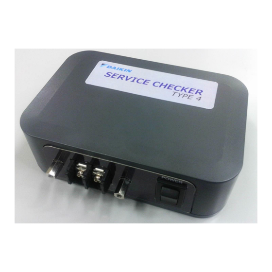
Functions, ways to use this software, and supported VRV models by this software are different based on software version. In this document, instructions are targeted at V1.2.1.1 or later version. PC software for TYPE3 Checker does not work with TYPE4 Checker. If you have not installed TYPE4 software to your PC, please obtain it before using. - Page 4 Service checker consists of two main components (TYPE4 checker box, TYPE4 checker software). It works with Windows PC which is connected to TYPE4 checker box by USB cable. It is necessary to install TYPE4 checker software to your Windows PC before using.
- Page 5 * Please use the USB cable which is included in the TYPE4 package. Connection port for D3-NET communication cable. D3-NET connection (This is not for power supply terminal, please do not apply power line. If you port connect power supply to this port, TYPE4 Checker box will be broken and burnt.)
-
Page 6: Preparation
1-2-1: Essential materials (TYPE4 checker) 1-2-2: D3-NET cable 1-2-1 Essential materials Standard components which are required for VRV operation data recording are below. 1. TYPE4 Checker box (Part number: 999176T) (1) TYPE4 Checker box (2) USB cable Connection cable for connecting Checker and PC... - Page 7 4. Wire the signal wires away from power lines to prevent the effects of electric noise. Since Daikin’s air conditioners and related products will generate much lower electric noises, it allows to have a distance of minimum 50mm between the power lines and the control signal wires.
- Page 8 AS0112-P-DENV 1-2-3 Required to do before recording After finishing preparation of materials, further preparation is needed for executed as the listed procedure. 1) TYPE4 software installation (setup) 2) Connecting PC and Checker 3) Confirmation of connection 4) Check of supported models 1) TYPE4 software installation (setup) Following the instruction of Chapter 2 (Installing the checker software), install checker software.
- Page 9 AS0112-P-DENV (2) Select COM port to be used in Select Port window Click top box and select COM port number to use. Please select COM port number which shows “Silicon Labs CP210x USB to UART Bridge” in the 2nd box. COM port number is different from PC.
-
Page 10: Obtainment Of Software (New/Update)
AS0112-P-DENV Chapter 2: Installing the checker software 2-1 Obtainment of software (new/update) Please obtain checker software from your Local Daikin Affiliate Business Portal webpage or ask your local Daikin affiliate/ distributor. (Reference) Daikin Europe Business Portal: https://my.daikin.eu •Software update When new VRV models introduced, it could be necessary to update checker software to check operation data of new model. - Page 11 •If the same version is installed, move to (10). 5) Select destination folder to install If you do not change, software will be installed to the below folder. •32bit OS:C:\Program Files\Daikin\Checker4\ •64bit OS:C:\Program Files(x86)\Daikin\Checker4\ To change installation folder, please install after change the system setting.
- Page 12 AS0112-P-DENV 7) When installation started, wait for the completion. 8) Installation completed 9) In start menu, “Daikin Service Checker TYPE4” will be added under “Daikin” folder and desktop. * Left picture is a sample of Windows7 PC * Looks of start menu display could differ from Windows version...
- Page 13 AS0112-P-DENV [Removal of software (uninstallation)] 10) If the same version software is installed, left window will be shown. Select Remove and press “Finish” If above screen will be shown, press Yes to proceed. 11) Software will be removed. 12) Software has been removed. (Note) * Even if the software will be removed, recorded data will remain.
-
Page 14: Removal Of Software
AS0112-P-DENV 2-3 Removal of software [Overview] There are two options for software removal. 1) From Windows control panel 2) By checker installation file (instructed by step (10) of 2-2 Installation procedure) 2-3-1 From Windows control panel Use this option if there is not installation file in your PC. (It is easier to uninstall from installer file for update) Procedure will be explained in below procedure with Windows7 and Windows10 sample. - Page 15 AS0112-P-DENV 3) Select Daikin Service Checker TYPE4 and click Uninstall 2. Click Uninstall 2. Click Uninstall 1. Select Daikin Service Checker TYPE4 1. Select Daikin Service Checker TYPE4 After this point, uninstall process will start. This process is same for Windows7 and 10.
-
Page 16: Connecting To The Unit
AS0112-P-DENV Chapter 3: Connecting to the unit [Warning] In case of long term logging or using in the outdoor under rainy weather, please take appropriate countermeasure for protection from rainwater to avoid electric shock or fire. 3-1 D3-NET (F1,F2) connection USB cable (included) TYPE4 checker box... -
Page 17: Connecting Power Supply
AS0112-P-DENV [Caution before using] •When connecting to the VRV unit for the first time, the unit will change to stand-by mode for several minutes to scan all the connected indoor and outdoor units. The system will automatically resume after finishing auto- scanning (for 2nd time and onwards, system would not enter stand-by status by choosing saved network map). -
Page 18: Start Up The Checker Software
1) From (Start[ button, select [Program] and select checker software. [ Windows 7 ] [ Windows 10 ] 2. Select “Daikin Service Checker TYPE4” 2.Select “Daikin Service Checker TYPE4” under Daikin folder 1. Click Start button 1. Click Start button 2) Checker software starts up and shows the main menu shown left. - Page 19 AS0112-P-DENV 2) By selecting “Setting”>”Exit”, checker software can be quit. 4-3 Overview of the checker software function There are buttons listed below are in the checker software main menu. Use for monitoring/recording VRV operation data [Record] (Refer to Chapter 5) Use for checking/exporting recorded data [Play] (Refer to Chapter 6)
-
Page 20: Recording Operation Data
AS0112-P-DENV Chapter 5: Recording operation data By [Record] menu, VRV operation data monitoring and recording (collecting data) can be executed. It is necessary to use this menu if case of only monitoring operation data without recording. Customer Network map Operation data As shown in the right chart, data is managed as System1: Mar.23 tree structure. - Page 21 AS0112-P-DENV • Press [New customer] to record data for a new customer with registration of customer information. Proceeding to [Customer data input] screen. Please proceed to (3) • To use existing customer information, please select desired customer and press [Select customer] button to proceed [Network map selection] screen.
- Page 22 AS0112-P-DENV • If there is network map which used for operation data recording in the past, please select desired network map and press [OK] button to proceed to [Network map] screen. Please proceed to [5-1-2: Network map display] • Even if in the site where you have recorded operation data before, if you are connecting to the different D3-NET system please press [New] button.
-
Page 23: Network Map Display
AS0112-P-DENV 5-1-2 Network map display Data will be collected upon the confirmation of previous screen. Status of data collection will be shown as icon in the network map. Checker software scans connected equipment in the D3-NET line for several minutes. (Note1) •Without initialization of D3-NET line after adding/removing outdoor unit, indoor unit, BS unit or replacing control PCB, network map cannot be shown. - Page 24 AS0112-P-DENV [Network map display] screen (1) How to read this screen • In this screen, outdoor and indoor units are shown as icon in the display order of auto- address • Icon color will change by status of units Color Status In unit error In communication error...
-
Page 25: Switching Modes
AS0112-P-DENV 5-1-3 Switching modes Buttons in the bottom row of the screen can be used by switching modes by buttons on the upper row at first then is pressed to execute desired function. A. Map mode Map mode Detail Data Input Centralized operation Update map [Detail Data Input]... - Page 26 AS0112-P-DENV C. Record mode Record mode Period. rec set Period. rec start [Periodic record set] Proceeding to “Periodic record set” screen and setup data recording to PC data drive. Please proceed to “5-2-1 Setup PC recording” [Periodic record start] By pressing this button, data recording to PC drive will start. On the upper left screen, “Period Rcd”...
-
Page 27: Detailed Info Input
AS0112-P-DENV 5-1-4 Detailed info input Detailed information such as installation place for each unit (icon). With this information, it becomes easier to identify each unit after second inspection onwards. [Detailed Data Input] screen Entry of detailed information is not obligatory. If it would not be utilized, there is no need to enter. - Page 28 AS0112-P-DENV (Note) •Once you replaced control PCB, auto address of network map will change. •If you updated map, location of detailed information will move from appropriate place because detailed info of each unit is stored in the order of auto address. To correct this situation please re-arrange detailed info as the procedure instructed below.
-
Page 29: Operation Data Display
AS0112-P-DENV 5-1-5 Operation data display [Operation data display] screen In [Network map display] screen, by pressing [Disp. op data] in [Display mode], operation data will be shown for selected system. 1 screen per 1 system will be shown. (1) Analog data graph (3) Present value of each parameter You can jump to the other... - Page 30 AS0112-P-DENV (3) Present value chart of each parameter (list on the right) Listed item Description (far left column) Colored square (□) is shown for parameter in the graph From lest, [data number], [classification of outdoor/indoor and number], [item Data item name] are displayed Operation data value is shown Data...
- Page 31 AS0112-P-DENV (4-2) Reloading data in (4) Inspection sheet display the sheet (4-3) Outdoor unit info and (4-1) Excel file data acquisition time is shown export (4-4) Manual input boxes (4-6) Auto filled from checker data (4-5) Select judgment result (4-7) Switch between outdoor units (4-1) Excel file export...
- Page 32 AS0112-P-DENV (4-6) Auto filled from checker data •Data box in pale blue background are data which would be filled automatically. •Upon creating inspection sheet window or clicking “(4-2) Reload data” button, selected operation values in [Operation data display] screen will be reflected. •By clicking you can enter values manually.
-
Page 33: Recording Setup
AS0112-P-DENV 5-2 Recording setup 5-2-1 Setup recording In [Network map display] screen, by pressing [Period. rec set] in [Record mode], [Periodic record set] screen will appear. [Periodic record set] screen 1. [Record mode] button 2. Press [Period. rec set] button 3. - Page 34 (4) If you need to manually stop periodic recording, press [Period. rec end] button. If you select [Auto] in [Record end method], recording will end in the set time automatically. (5) In case of disconnection of communication with TYPE4 Checker box, [Communicating(Error)] will be shown. Please check connection and retry recording.
-
Page 35: Centralized Operation
If the centralized group number is not set yet, it is necessary to set them. Connect TYPE4 checker box to D3-NET line and setup customer information from checker software, please show [Network map display] screen. With this condition, centralized operation will be possible if you set necessary centralized group number by indoor unit remote controller. - Page 36 AS0112-P-DENV [Procedure] (1) Select desired indoor unit icon and execute centralize operation such as alteration of set values, etc. Button, box Description Start selected unit Stop Stop selected unit Change setpoint, range of value is 0 to 35. * If specification of unit has value range of 16-32, even though you changed ...
-
Page 37: Playback Of Recorded Operation Data
AS0112-P-DENV Chapter 6: Playback of recorded operation data 6-1 Playing operation data [Procedure] (1) In main menu, press [Play] button to proceed to [Customer data selection] screen. Press [Play] button (2) Please select desired operation data and highlight. Select desired data to open [Disp. - Page 38 AS0112-P-DENV (3) Operation data display screen * Details of operation data display, please refer to “5-1-5 Operation data display”. If you click on the graph area, parameters on that time will be listed on the right. Buttons listed below will work for the graph displayed on the left.
- Page 39 AS0112-P-DENV (5) Inspection sheet can be created by pressing button in the bottom of this screen. Create inspection sheet • Please refer to [5-1-5 Operation data display] for details of inspection sheet (6) By pressing [Back] button to customer data selection screen.
-
Page 40: Viewing Customer/Network Map Information
AS0112-P-DENV 6-2 Viewing customer/network map information Customer information and network map (system/line information) can be checked by recorded data. By this data, it is possible to check customer/customer’s VRV system, model information stored in PC. [Procedure] (1) In main menu, press [Customer data] button to proceed to [Customer selection] screen. Press [Customer data] button (2) Customer selection screen Press [Select customer] button to proceed to [Network map selection] screen... - Page 41 AS0112-P-DENV (4) Network map display screen [System], [System]: Move between systems [Detail Data Input]: Press in case of model/installation place info input Please proceed to [5-1-4 Detailed info input] [Back]: Return to [Network map selection]...
-
Page 42: Csv Output (Export Function)
AS0112-P-DENV 6-3 CSV output (export function) To utilize recorded data by the other software such as Excel, data export to csv format is supported. *CSV format: comma separated value data [Procedure] (1) In main menu, press [Play] button to [Customer data selection] screen Press [Play] button (2) [Customer data selection] screen Select desired data and press [CSV data output] button... - Page 43 AS0112-P-DENV CSV file output period setting All data output All recorded data will be exported to csv file Narrow down data period which will be exported to csv Select Output data (reduction of export time and file size) Header data setting Export site, equipment, data information header to csv file Data only export without header rows (good for auto process by the other tools)
- Page 44 AS0112-P-DENV Chapter 7: Other functions 7-1 Data transfer Recorded operation data or customer data can be transferred or sent by the storage media such as USB stick drive. To execute this, [Data transfer] function is used. (Note) •Data can be copied directly from PC folder location by Windows explorer, it is not easy to locate them so it’s much more convenient to use this function.
- Page 45 AS0112-P-DENV 1. Transfer operation data and customer information Exporting data (to storage media) 1. Select operation data or customer information on the left to transfer. 2. Select destination folder in the right side of the screen. 3. By pressing right arrow [➔] button to start transferring. Importing data (from storage media or folder) 1.
-
Page 46: Customer Information
AS0112-P-DENV 7-2 Customer information Checker software manages operation data by customer basis. Therefore customer ID is mandatory field to enter in customer information. If the operation data is recorded from [Record only] without managing data by customer information, every time VRV unit will be D3-NET initialization status and thermostat-OFF condition. -
Page 47: Option Setting
Note) In case of no COM port with “Silicon Labs CP210x USB to UART Bridge” It is necessary to install driver files of USB serial port. Please obtain appropriate driver installer files from your local Daikin representative, or could be downloaded from below URL. -
Page 48: Prohibit/Permit Centralized Control
AS0112-P-DENV 7-3-2 Prohibit/permit centralized control It is possible to stop sending centralized control command from checker by this setting. Checker has a centralized operation function, it regularly transmits data as a centralized controller to the connected D3-NET line. To prohibit centralized control by this function, data transmission as centralized controller can be stopped by checker. -
Page 49: Change Display Language
AS0112-P-DENV 7-3-3 Change display language GUI language can be switched in between Japanese, English, and Simplified Chinese. Change will take effect after restarting the software. (By change of language, some units could not be correctly monitored due to model info incompatibility) Change GUI language from [Settings] >... - Page 50 7-4 Help function By help function, information listed below can be checked. Display help screen (1) Help Show wiring guidance screen to show how to connect TYPE4 checker (2) Connection guide and VRV (3) Support models Supported model list can be checked by PDF file.
- Page 51 AS0112-P-DENV 3) Supported model PDF viewer 4) Version info Software version can be checked...
- Page 52 AS0112-P-DENV Frequently asked questions ◼ D3-NET related topic [Q-101] Error is generated if checker is connected to the system which Wiring Adaptor for Electrical Appendices (1) or (2) (KRP2A or KRP4A) adapter is installed. [Phenomenon] The other supervising system (BMS) controls VRV via Wiring adapter for electrical appendices and checker is connected to this system, supervising system causes air conditioner error.
- Page 53 AS0112-P-DENV ◼ Software related topic [Q-201] About software update [Countermeasure] Download update software from Daikin Europe Business Portal site: https://my.daikin.eu [Q-202] When trying to install the checker software, alert dialog is shown and installation cannot be executed. [ Windows 7 ]...
- Page 54 AS0112-P-DENV [Q-203] About frequently asked error message and possible actions (communication between PC and checker) [Error: 5-3] Message Port could not be opened. Selected COM port number does not match with actual COM port which is Probable connected to the checker. Default setting of COM port number is “COM1”. causes If the checker is connected to the other port number, your PC cannot communicate with the checker.
- Page 55 AS0112-P-DENV ◼ Unit related topic [Q-301] All parameters persist on same value (do not change at all) [Cause] Checker records operation data received from VRV units, but if no communication data comes, the last parameters which was correctly received are recorded instead of blank, - - , or 00. Thus if there is no data is available due to disconnected wiring or electric interference, same value (last correctly received data) is recorded after this point.
- Page 56 AS0112-P-DENV Specification Specification list of TYPE4 Checker Item Spec Dimension 125(W) x 85(D) x 40(H) mm Weight 200g (approximately) Power supply 5V DC 200mA 1W (approximately) Power input Operating temp/RH -10~55 deg, 95%RH or below (only except for condensation status)
Need help?
Do you have a question about the TYPE4 Checker and is the answer not in the manual?
Questions and answers