Table of Contents
Advertisement
Quick Links
Advertisement
Table of Contents

Subscribe to Our Youtube Channel
Related Manuals for Market Forge Industries M24SC


Summary of Contents for Market Forge Industries M24SC
- Page 1 OWNER’S MANUAL MODULAR STEAM COIL BOILER MODELS: ● M24SC ● M36SC ● Form No. S-5046C 05/10 An Employee Owned Company 35 Garvey Street Everett MA 02149-4403 ● ● ● Tel: (617) 387-4100, (866) 698-3188 Fax: (617) 387-4456, (800) 227-2659 ● custserv@mfii.com www.mfii.com ●...
-
Page 2: Table Of Contents
TABLE OF CONTENTS INTRODUCTION ....................... 1 OPERATION ......................1 INSTALLATION RECEIVING INSTRUCTIONS ................1 SETTING IN PLACE .................... 1 INSTALLING LEGS .................. 1 LEVELING ....................1 PANELS AND DOORS ................1 IMPORTANT INFORMATION ON STEAM COIL STEAM GENERATORS TO STEAM FITTER ....................1 SERVICE CONNECTIONS.................. 2 BOILER HORSEPOWER AND STEAM FLOW INFORMATION ......3 STEAM FITTER AND PLUMBER ................ 4 STEAM CONNECTION ................4 SETTING OF STEAM GENERATOR PRESSURE CONTROL SWITCHES (ON MODELS BEFORE 1979) ................4 PRESSURE CONTROL SWITCH ADJUSTMENT (ON MODES AFTER 1979) . . 6 WATER LEVEL CONTROL (ON MODELS BEFORE 1984) ........ -
Page 3: Introduction
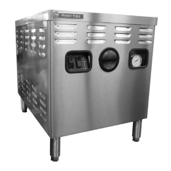
INTRODUCTION Polished stainless steel cabinet base shall be of modular combustable wall. Steam generator shall be ASME con- design to match other Market Forge cooking equipment, structed of 15 PSI operation. and equipped with 6” 152mm stainless steel legs, adjust- able bullet feet, reinforced stainless steel counter-top and Steam generator shall be automatically filled with cold stainless steel lift-off front panel. water and brought to pressure when heat and water switches are turned on and automatically drain under Stainless steel steam coil generator equipped for opera- pressure shall automatically condense exhausted steam tion at 15 PSI (1kg/cm ). Unit shall include as standard an into water before releasing it to drain. automatic drain, cold water condenser, automatic water level control, low water cut off, pressure control, air vent, OPERATION: and a safety relief valve. -
Page 4: Service Connections
INSTALLATION... -
Page 5: Boiler Horsepower And Steam Flow Information
INSTALLATION but not, considered clean enough to come in contact with TABLE 2: food. Toxic steam generator cleaning compounds are of- Steam ten used to clean steam generators, and this is usually Delivered Flow Lbs. Boiler Steam Per the reason for not recommending direct connected cook- H.P. Hour ers. Compartment Steam Cookers 34.5 (per compartment) It is very important that a minimum of 15 PSI be available Steam Jacketed Kettles (Per 20 gallons) 34.5 in the incoming steam line if a steam coil steam generator is to be installed for use with a 5 PSI compartment cooker. Direct Connect Steam-It 17.25 If the equipment connected to the steam generator oper- TABLE 3: ates at 15 PSI, minimum incoming pressure must be 30 Follow of steam in pipe, in pounds of steam per inch. PSI, except in the case of a single Steam-It, which can be operated on an incoming pressure of 20 PSI. Maximum Line pressure recommended incoming steam pressure is 50 PSI. (the in lbs. per Pipe Size in inches square inch table below) shows Boiler Horse Power (BHP) generated... -
Page 6: Steam Fitter And Plumber
INSTALLATION length of run of 41.4 feet of straight pipe. SUGGESTED STEAM CONNECTIONS: Figure 2 Actual run 20 feet. Equivalent run 41.4 feet. Rate of flow 240 pounds of steam per hour. TABLE 4: Resistance of fittings expressed in terms of Figure 3 equivalent length of straight pipe. (Measurements are in feet) ITEM DESCRIPTION PART # 3/4” Globe Valve 10-2821 Side Ball Float Trap 10-5336 Pipe Standard Outlet Gate Globe Angle Size Elbow Valve Valve... - Page 7 INSTALLATION and should not be adjusted unless absolutely nec- essary. If pressure is found to be other then above, proceed as follows. • Remove front cover from modular control box. • With screwdriver adjust pressure switches (A) and (B). Steam col steam generators used to generated steam for a Steam-It, Steam Cooker or Kettle which operate at 15 PSI should be set as follows: Switch (A) should be steam at 12 PSI and switch (B) should be set at 20 PSI. If 15 pounds steam generator is used for 5 pounds operation, follow above instructions and then...
-
Page 8: Pressure Control Switch Adjustment (On Modes After 1979)
INSTALLATION PRESSURE CONTROL SWITCH ADJUSTMENT (on models after 1979): Refer to figure 5 on page 5. If generator fails to maintain steam pressure in operating range, pressure control switch may require adjustment. Start generator and allow pressure to build up to op- erating level - 15 PSI. Check generator pressure gauge. If gauge indicates Figure 6 12 to 14 PSI, pressure control switches are properly adjusted. CAUTION: Before removing cover disconnect 115V pow- If generator does not come on when pressure gauge er supply. When the boiler is full, water level should reach reads 12 PSI and does not go off when pressure 2/3 full in gauge glass and the water feed should shut off. gauge reads 14 PSI, proceed as follows: If this is not correct, remove cover to water level control •... -
Page 9: Water Level Control (On Models After 1984)
INSTALLATION Remove the two screws (B) on either side of housing. The housing, with all external wiring still attached, may then be removed to one side. Figure 8 With an allen set screw wrench remove the set screws at the four corners of the mounting plate. Pull out and remove the complete float assembly and gasket from the boiler. Clean the internal boiler parts of the water level con- trol. Use a tooth brush to clean the bellows. If the deposits are excessive, a flat blade putty knife may be used to clear accumulations from between the bellows fins. However, care should be used not to rupture them or twist bellows out of alignment. When satisfied that the complete float switch assembly is... -
Page 10: Wiring Diagrams
INSTALLATION... - Page 11 INSTALLATION...
- Page 12 INSTALLATION...
- Page 13 INSTALLATION...
- Page 14 INSTALLATION...
- Page 15 INSTALLATION...
- Page 16 INSTALLATION...
-
Page 17: Operation
OPERATION INDICATOR LIGHT WATER SWITCH HEAT SWITCH WARNING: DO NOT HOSE DOWN UNIT AS IT CONTAINS ELECTRICAL COMPONENTS. START UP: UNITS MANUFACTURED AFTER 1983, There are two methods of draining steam generators; EQUIPPED WITH “MOMENTARY” HEAT SWITCH: one is automatic and the other is manual. To determine Daily Operating Instructions: which method the unit has, open cabinet doors and there Flip water switch on. -
Page 18: Trouble-Shooting
TROUBLE-SHOOTING TROUBLE-SHOOTING GUIDE: BOILER FAILS TO REACH FULL OPERATING PRESSURE OF 5 OR 15 POUNDS. PRESSURE GAUGE READS INACCURATELY. REPLACE. PRESSURE CONTROL AND HIGH LIMIT CONTROL SWITCH- FOLLOW INSTRUCTIONS FOR ADJUSTING. ES ARE OUT OF ADJUSTMENT. CLEAN OR REPLACE. SAFETY VALVE NOT SEATING PROPERLY. ADJUST WATER LEVEL CONTROL. A) CHECK WATER FEED WATER LEVEL TOO HIGH. VALVE FOR STICKING. B) CLEAN OR REPLACE. STEAM TRAP ON UNITS RECEIVING STEAM FROM BOILER REPLACE ELEMENT IN STEAM TRAP OF UNIT BEING FED NOT CLOSING SUFFICIENTLY AFTER VENTING. STEAM FROM BOILER. AIR VENT AND VACUUM BREAKER NOT VENTING PROP- REPLACE. - Page 19 TROUBLE-SHOOTING SOLENOID STEAM VALVE FAILS TO OPEN. LACK OF POWER TO UNIT. CHECK 110V POWER SUPPLY. DIRTY SEAT IN SOLENOID VALVE. CLEAN VALVE. INOPERABLE SOLENOID VALVE. CHECK COIL. REPLACE IF NECESSARY. WATER DOES NOT ENTER BOILER. WATER MAIN SHUT OFF. TURN ON. POWER NOT REACHING SOLENOID WATER FEEDER. CHECK MAIN FUSE AND IF 115V IS PRESENT AT WATER DEFECTIVE WATER MICROSWITCH IN WATER LEVEL CON- FEEDER. TROL BOX OR LOOSE CONNECTION. CHECK CONTINUITY OR LOOSE CONNECTION, REPLACE WATER LEVEL CONTROL MICROSWITCH OUT OF ADJUST- LEFT SWITCH IF DEFECTIVE. MENT. FOLLOW INSTRUCTIONS FOR READJUSTING LEFT MICRO- DIRT OR LIME ON SEAT OF RIGHT SOLENOID VALVE IN SWITCH. IF ADJUSTING OR CLEANING DOES NOT REMEDY, CONTROL BOX.
-
Page 20: Illustrated Parts
ILLUSTRATED PARTS WATER LEVEL AND STEAM CONTROL ITEM PART # DESCRIPTION 09-4887 McDONNELL LOW WATER CUT OFF (ON UNITS AFTER 1984) 90-8929 MARKET FORGE LOW WATER CUT OFF (ON UNITS BEFORE 1984) 10-4612 GAUGE GLASS 10-4576 GAUGE GLASS ASSY WITH GAURDIAN RODS - R. H. 10-3474 COUPLING, PLAIN, R. H. SCREWED 1/2” 10-4556 AIR VENT 91-3311 REWORKED STEAM TRAP 10-5785 HAYS SOLENOID STEAM VALVE NC 115V 10-6452 HAYS SOLENOID STEAM VALVE NC 240V... -
Page 21: Plumbing
ILLUSTRATED PARTS PLUMBING ITEM PART # DESCRIPTION 91-3312 DRAIN SUB ASSY 91-2119 DRAIN LINE - STEAM TRAP TO DRAIN TERMINAL 36” CABINET 91-2118 DRAIN LINE - STEAM TRAP TO DRAIN TERMINAL 24” CABINET 91-2115 ANTI-SYPHON PRESSURE SWITCHES - 36” CABINET 91-2114 ANTI-SYPHON PRESSURE SWITCHES - 24” CABINET... -
Page 22: Control Box
ILLUSTRATED PARTS CONTROL BOX ITEM PART # DESCRIPTION 91-5374 120V CONTROL BOX ASSY 91-5373 120V CONTROL BOX ASSY, FOR USE WITH A-PLUS COOKER ONLY 91-5376 230V CONTROL BOX ASSY 91-5371 230V CONTROL BOX ASSY, FOR USE WITH A-PLUS COOKER ONLY 10-5163 HANDY BOX 10-5164 HANDY BOX COVER 10-4634 RELAY TIME DELAY 120V 10-6970 RELAY TIME DELAY 240VSOCKET RELAY 10-6512 SOCKET RELAY 10-8411 SWITCH PRESSURE BARKSDALE E15-F15-PLS 10-8410 SWITCH PRESSURE BARKSDALE E15-H15-PLS 91-6085 PRESSURE SWITCH ASSY, ITEMS 5 + 6 10-5184 STRIP TERMINAL 10-4653 THERMOSTAT 10-6169 PILOT LIGHT 10-5022 SPST SWITCH 10-5484 DPDT SWITCH 10-0865... -
Page 23: 24" Cabinet
ILLUSTRATED PARTS 24” CABINET ITEM PART # DESCRIPTION 90-2657 REAR PANEL STAINLESS STEEL 90-2658 REAR PANEL ENAMEL 90-2661 SIDE PANELS RIGHT AND LEFT STAINLESS STEEL 90-2659 SIDE PANELS RIGHT AND LEFT ENAMEL 90-2662 SIDE PANELS RIGHT AND LEFT STAINLESS STEEL (GAS MODEL) 90-2660 SIDE PANELS RIGHT AND LEFT ENAMEL (GAS MODEL) 10-0631 90-8974 ASSY, 24” x 33” MODULAR FRAME 90-2993 DOOR ASSY, STAINLESS STEEL 90-2996 DOOR ASSY, ENAMEL 90-2663 PANEL MTG, BRACKET 10-0493 FEATURE STRIP 90-3210 BRACKET - MAGNETIC CATCH 10-5561 MAGNETIC CATCH 90-9057 DOOR HANDLE 10-2422 SPECIAL WASHER 10-1869 NO 10-32 x 1/2” FLAT HEAD SCREW 10-0454 CABINET HINGE RIGHT BOTTOM... -
Page 24: 36" Cabinet
ILLUSTRATED PARTS 36” CABINET ITEM PART # DESCRIPTION 90-2663 PANEL MTG, BRACKET 10-2511 WASHER 10-2147 HEX NUT 90-2657 REAR PANEL STAINLESS STEEL 90-2658 REAR PANEL ENAMEL 10-0631 90-2661 SIDE PANELS RIGHT AND LEFT STAINLESS STEEL 90-2659 SIDE PANELS RIGHT AND LEFT ENAMEL 90-2662 SIDE PANELS RIGHT AND LEFT STAINLESS STEEL (GAS MODELS) 90-2660 RIDE PANELS RIGHT AND LEFT ENAMEL (GAS MODELS) 90-3185 DOUBLE WASHER 90-9023 ASSY, 36” x 33” MODULAR FRAME 10-0454 CABINET HINGE R. BOTTOM 10-1869 NO 6-32 x 1/2” ROUND HEAD MACHINE SCREW 10-2422 WASHER 90-9070 DOOR ASSY, ENAMEL 90-9062 DOOR ASSY, STAINLESS STEEL 90-9057 DOOR HANDLE...
Need help?
Do you have a question about the M24SC and is the answer not in the manual?
Questions and answers