
Related Manuals for Sferalabs Iono Pi Max Series


Summary of Contents for Sferalabs Iono Pi Max Series
- Page 1 Iono Pi Max User Guide September 2020 Revision 003 ICMX10XS Iono Pi Max Solo ICMX10XPL Iono Pi Max 3+ Lite ICMX10XP1 Iono Pi Max 3+ 8GB ICMX10XP2 Iono Pi Max 3+ 16GB ICMX10XP3 Iono Pi Max 3+ 32GB ...
-
Page 2: Table Of Contents
Safety information Qualified personnel Hazard levels Safety instructions General safety instructions Battery Introduction Features Hardware setup Device identification Connections Opening the case Closing the case Raspberry Pi Compute Module installation How to flash the eMMC microSD installation The external UPS battery Replacing the RTC backup battery Terminal blocks Power supply... - Page 3 ATECC608A secure element EERAM Push button LEDs Power supply Shutdown enable mode Shutdown wait time Power-off time Power-up delay Power-up mode UPS and battery charger Auxiliary voltage outputs Hardware watchdog Internal fan and temperature sensors Analog inputs AVx: Analog voltage inputs AIx: Analog current inputs ATx: Temperature sensors inputs AOx: Analog voltage and current outputs...
- Page 4 Safety instructions Set-up Conformity Information CANADA RCM AUSTRALIA / NEW ZEALAND Iono Pi Max User Guide...
- Page 5 The product information on the web site or materials is subject to change without notice. Please download and read the Sfera Labs Terms and Conditions document available at: http://www.sferalabs.cc Iono and Sfera Labs are trademarks of Sfera Labs S.r.l. Other brands and names may be claimed as the property of others.
-
Page 6: Safety Information
Safety information Carefully and fully read this user guide before installation and retain it for future reference. Qualified personnel The product described in this manual must be operated only by personnel qualified for the specific task and installation environment, in accordance with all relevant documentation and safety instructions. -
Page 7: Safety Instructions
Safety instructions General safety instructions Protect the unit against moisture, dirt and any kind of damage during transport, storage and operation. Do not operate the unit outside the specified technical data. Never open the housing. If not otherwise specified, install in closed housing (e.g. distribution cabinet). -
Page 8: Battery
Battery Iono Pi Max uses a small lithium non-rechargeable battery to power its internal real time clock (RTC). WARNING Improper handling of lithium batteries can result in an explosion of the batteries and/or release of harmful substances. Worn-out or defective batteries can compromise the function of this product. Replace the RTC lithium battery before it is completely discharged. -
Page 9: Introduction
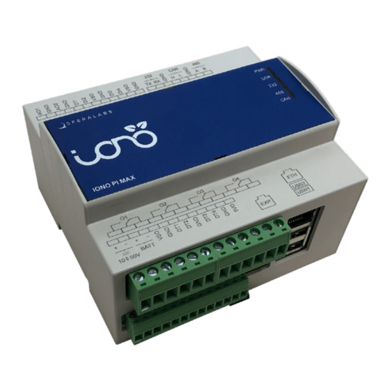
Introduction Iono Pi Max is an extremely versatile industrial server with a huge variety of Input/Output lines and standard communication interfaces, based on the Raspberry Pi Compute Module, suitable for use in professional and industrial applications where reliability and service continuity are key requirements, and housed in a compact 6 modules DIN rail case. -
Page 10: Features
Features Iono Pi Max, all versions: ✓ compatible with Raspberry Pi Compute Module 3, Raspberry Pi Compute Module 3 Lite, Raspberry Pi Compute Module 3+ 8GB, Raspberry Pi Compute Module 3+ 16GB, Raspberry Pi Compute Module 3+ 32GB, Raspberry Pi Compute Module 3+ Lite ✓... - Page 11 Pi board and acting on the Raspberry Pi Compute Module hardware reset line. The hardware watchdog can also control the microSD switch matrix, swapping the boot card in case the watchdog is triggered ✓ powerful and user-programmable 32 bit microcontroller (ATSAME54), with 1 MB program memory and 256 KB RAM.
-
Page 12: Hardware Setup
Hardware setup Device identification The device can be identified with the information provided in the rating and identification plate, permanently attached to the side of the case. EXAMPLE RATING AND IDENTIFICATION PLATE Connections IONO PI MAX CONNECTION EXAMPLE Iono Pi Max User Guide... -
Page 13: Opening The Case
For the initial set-up, the plastic DIN rail enclosure must be removed to access the circuit boards and internal connectors, to install or remove the Raspberry Pi Compute Module and the µSD cards. The case also needs to be opened if the factory configuration of the RS-485 and CAN termination resistors must be changed (see below), or to connect to the microcontroller programming and debug header. -
Page 14: Raspberry Pi Compute Module Installation
OPENING AND CLOSING THE CASE Raspberry Pi Compute Module installation To install your own Compute Module in Iono Pi Max Solo, or replace the pre-installed module, no tools are required once the plastic enclosure has been removed and the circuit boards assembly is exposed. -
Page 15: The External Ups Battery
When the Compute Module Lite is installed, as it lacks an internal eMMC chip, one of the two microSD slots will be used as the boot SD card, just like with a Raspberry Model B board. The other microSD can be used as additional storage. Dedicated commands to the microcontroller allow to select which slot is used for boot, and if the other is enabled or not. -
Page 16: Replacing The Rtc Backup Battery
Follow the battery manufacturer's instructions when installing the external UPS battery (not provided). Replacing the RTC backup battery Iono Pi Max has a hardware real time clock with a dedicated long-life non-rechargeable back-up battery. Iono Pi Max is shipped with a CR1220 Lithium / Manganese Dioxide (Li/MnO2) battery installed. - Page 17 Once the circuit boards assembly is extracted from the enclosure, the most convenient way to access the battery holder is to first separate the vertical board from the base board. This is easily accomplished by unscrewing the two screws on the bottom side of the base board, that secure the vertical board to it.
-
Page 18: Terminal Blocks
RTC BACKUP BATTERY INSTALLED Terminal blocks Iono Pi Max has several pluggable terminal blocks. All power supply, input/output and serial interfaces are on 3.81mm pitch terminal blocks. The maximum conductor cross section is 1.31 mm (16 AWG), or 0.5 mm when using ferrules (highly recommended). -
Page 19: Power Supply
THE IONO PI TOP CIRCUIT BOARD WITH TERMINAL BLOCKS Power supply Iono Pi Max can be powered with DC voltage only: ✓ DC: nominal voltage range 10.0V to 50.0V. Respect the correct polarity shown in the schematic diagram (+ -). The power supply circuit implements reverse polarity protection using auto resetting fuses and surge protection up to ±1000V (line to earth, common mode) 1.2/50μs. -
Page 20: Battery Charger
Battery charger The Iono Pi Max UPS (uninterruptible power supply) implements a programmable battery charger, that can charge an external lead-acid battery (other chemistries could be supported with future firmware releases). The battery line is protected by an internal 3.3A resettable fuse. You can use either 12V or 24V batteries. -
Page 21: Software Installation And Configuration
Software installation and configuration All features of Iono Pi Max can be used with any operating system, programming language or framework compatible with Raspberry Pi. The following sections describe how to install utility drivers for the Raspberry Pi OS (formerly Raspbian) or to access its features from alternative set-ups. Raspberry Pi OS Kernel module The Iono Pi Max Kernel module can be used to easily access all of Iono Pi Max features via a sysfs file system. -
Page 22: Raspberry Pi Os Socketcan Driver
You may want to remove the "fake-hwclock" to avoid conflicts: $ sudo apt autoremove --purge fake-hwclock Download and run the installation script: $ wget https://sferalabs.cc/files/ionopimax/rtc-install $ chmod 755 rtc-install $ sudo ./rtc-install After completion, delete the installation script and reboot:... -
Page 23: Alternative Set-Up
$ dtc -@ -Hepapr -I dts -O dtb -o ionopimax-can-fd.dtbo ionopimax-can-fd.dts $ sudo cp ionopimax-can-fd.dtbo /boot/overlays/ $ cd mcp25xxfd $ sudo ./install.sh Add to /boot/config.txt the following line: dtoverlay=ionopimax-can-fd Reboot: $ sudo reboot After reboot you should see a new "can0" interface available: $ ifconfig -a can0: flags=193<NOARP>... -
Page 24: Using Iono Pi Max
Using Iono Pi Max Most of the features discussed in this chapter are based on features implemented on our firmware code, version 1.0, running on the SAME54 microcontroller. The microcontroller can be programmed with user developed custom firmware, that could replace the factory installed version. - Page 25 The IGND terminal is the isolated ground reference for the RS-485 serial lines. Always use this line, not GND, for the RS-485 connection. The RS-485 TX/RX switching is implemented automatically in the Iono Pi Max microcontroller, based on the USB serial device speed and number of bits settings, and is completely transparent to the software on Raspberry Pi.
-
Page 26: Can Fd Port
RS-485 JUMPERS AND SWITCH POSITION CAN FD port The CAN interface is based on the Microchip MCP2518FD CAN FD Controller and the Microchip MCP2558FD high-speed CAN FD transceiver. They implement both CAN 2.0B and CAN FD modes, with support for up to 8 Mbps data rate and 1 Mbps arbitration rate. The CANH and CANL lines are available on the terminal block. -
Page 27: Exp Port
CAN TERMINATION JUMPER POSITION EXP port The EXP port is a proprietary 5V bidirectional I2C interface exposed on a 6-position RJ12 socket that can be used to connect external devices. NOTICE All lines of the EXP port are at 5V level. Do not connect incompatible devices, like 3.3V I2C devices, telephone equipment or any other device not specifically designed to be connected to this proprietary port. -
Page 28: Sd Matrix
Pin # Description 5 VDC out AUX in/out (active low) EXP INTERFACE PLUG PINS SD matrix Iono Pi Max implements a flexible dual microSD card architecture. Iono Pi Max routes its two microSD card holders to the Compute Module through a high- speed switching matrix, controlled by the on-board microcontroller. - Page 29 NOTICE Disconnecting an SD card from the Compute Module's SD interfaces when partitions from the card are mounted at the operating system level, can result in file system and data corruption. The Iono Pi Max matrix and the microcontroller don't check for card usage and don't provide any safety mechanism to prevent improper disconnection of the SD cards.
-
Page 30: Usb Ports Power Management
SD MATRIX BOOT FROM SDB Finally, with the SDX interface connected to SDB for boot, the SDA slot can be enabled to be used for additional storage. SD MATRIX BOOT FROM SDB AND SDA ENABLED FOR ADDITIONAL STORAGE It is also possible to disable both the SDX and SD1 interfaces. This configuration could be used with the Compute Module versions that have the embedded eMMC storage, when no external SD card is needed. -
Page 31: Atecc608A Secure Element
USB PORTS These ports are individually controlled by the MIC2076, a power distribution controller with circuit protection. The MIC2076 is internally current limited and has thermal shutdown that protects the device and load (0.5A max). A fault status output flag is asserted during over- current and thermal shutdown conditions. -
Page 32: Eeram
✓ Networking key management support ✓ Turnkey PRF/HKDF calculation for TLS 1.2 & 1.3 ✓ Ephemeral key generation and key agreement in SRAM – Small message encryption with keys entirely protected ✓ Secure boot support ✓ Full ECDSA code signature validation, optional stored digest/signature – optional communication key disablement prior to secure boot ✓... -
Page 33: Power Supply
Each LED has controllable general brightness, and independent brightness control of the primary red, green and blue colors. The sysfs control files are l<n>_br, l<n>_r, l<n>_g and l<n>_b in the led/ directory (I2C control registers 105-108, 110-113, 115-118, 120-123, 125-128 for CAN, RS-485, RS-232, USR and PWR). When the user changes any of the control registers, that specific color or brightness level is released for exclusive user's control, and will not be driven again, until the microcontroller is reset, to provide the default indications. -
Page 34: Shutdown Wait Time
Shutdown wait time Set the shutdown wait time, in seconds. The factory default is 60 seconds, configurable with the power/down_delay file (I2C control register 37). Power-off time Set the power-off time, in seconds. The factory default is 5 seconds, configurable with the power/off_time file (I2C control register 38). -
Page 35: Auxiliary Voltage Outputs
Starting from a power off condition, Iono Pi Max will not power-up if only the back-up battery is connected. Battery voltage and charge current can be monitored reading files ups/charger_mon_v, in mV (I2C control register 147), and ups/charger_mon_i, in mA (I2C control register 148). Note that, when Iono Pi Max is being powered by the UPS battery, ups/charger_mon_v continues to show the battery voltage, while ups/charger_mon_i returns a value close to zero. -
Page 36: Internal Fan And Temperature Sensors
Watchdog default behavior is described below, but all timing parameters and control logic can be modified through the I2C control registers and sysfs files. The watchdog is normally disabled. To enable it, set GPIO39 pin to high. While GPIO39 is high, the Iono Pi Max controller will watch for state changes of the GPIO32 heartbeat pin. -
Page 37: Avx: Analog Voltage Inputs
The analog section of Iono Pi Max is enabled by default, but can be disabled, turning off the dedicated isolated DC-DC converter, the ADC and the analog front-end stage. The sysfs analog enable file is analog_in/enabled (I2C control register 69). The firmware also controls a high-speed filter for the analog voltage and current inputs. -
Page 38: Atx: Temperature Sensors Inputs
ATx: Temperature sensors inputs Iono Pi Max has two inputs dedicated to connect two-wire resistance temperature sensors (RTD). Both Pt100 and Pt1000 standard sensors are supported. To use these inputs, you should first set the sensor type in analog_in/at<n>_mode (I2C control register 69). -
Page 39: Dtx: Digital Input/Output (Wiegand, 1-Wire)
NOTICE The OCx outputs can operate with positive voltage levels up to 50Vdc. Applying out of range voltages could damage the product and connected devices. NOTICE Open circuit fault detection is implemented in the MAX4896 by a pulldown current source, along with a voltage comparator, which keeps a small current flowing when the contact is open. -
Page 40: Ox: Relays
Ox: Relays Iono Pi Max has four relays with change-over (CO), Single Pole Double Throw (SPDT) terminals, with normally open (NO) and normally closed (NC) contacts, driven by a Maxim MAX4896 8-channel relay and load driver. digital_out/o<n> files (I2C control registers 84-85) are used to set the relays status, and read the status and error conditions. -
Page 41: Advanced Usage
Advanced usage Dedicated GPIO pins Iono Pi Max uses several of the Raspberry Pi Compute Module GPIO pins. These pins should not be used for other functions. GPIO pin Direction Description GPIO2/SDA1 C SDA line GPIO3/SCL1 C SCL line GPIO14/TXD serial TX line (RS-232 or RS-485) GPIO15/RXD serial RX line (RS-232 or RS-485) -
Page 42: Raspberry Pi I2C Bus Addresses
GPIO pin Direction Description GPIO34 in/out GPIO35 in/out GPIO36 in/out GPIO8 SPI0 CE0 (CAN controller CS) GPIO9 SPI0 MISO (CAN controller SDO) GPIO10 SPI0 MOSI (CAN controller SDI) GPIO11 SPI0 CLK (CAN controller SCK) GPIO22 SD1 CLK GPIO23 SD1 CMD GPIO24 in/out SD1 DAT0... -
Page 43: I2C Configuration And Control Registers Map
I2C Configuration and control registers map FIRMWARE VERSION ADDR BYTE 1 BYTE 0 MAJOR MINOR Register 1 Bit 7-0 MINOR: minor version of the installed firmware Bit 15-8 MAJOR: major version of the installed firmware MCU COMMANDS ADDR BYTE 1 BYTE 0 BUSY FAIL... - Page 44 EXP I2C BRIDGE ADDR BYTE 1 BYTE 0 PI SIDE ADDRESS OP CODE DEVICE ADDRESS Register 17 Bit 6-0 PI SIDE ADDRESS: I2C address mapped to the Raspberry Pi's I2C bus In order to create or delete an entry in the I2C addresses translation table, write here the I2C address as seen on the Raspberry Pi's I2C bus, to be mapped to the EXP bus.
- Page 45 Register 32 Bit 15-0 SD SWITCH: SD switch control after power cycle triggered by watchdog 0 = SD switch disabled (default) N > 0 = switch boot from SDA/SDB after N consecutive watchdog resets, if no heartbeat is detected. A value of N > 1 can be used with MOD set to 1 only;...
- Page 46 Register 39 Bit 15-0 UP DELAY: power-up delay after main power is restored, in seconds (default = 0) ADDR BYTE 1 BYTE 0 VOLT CAPACITY MAX CURRENT DOWN DELAY CHARGE STAT Register 43 Bit 0 EN: UPS control 0 = disabled 1 = enabled (default) Bit 1 BAT VOLT: battery voltage...
- Page 47 1 = detecting battery 2 = battery disconnected 4 = charging battery 5 = battery charged 6 = battery in use 8 = battery overvoltage error 9 = battery undervoltage error 10 = charger damaged 11 = unstable Bit 7 BAT: battery/main power 0 = running on main power 1 = running on battery power...
- Page 48 ANALOG INPUTS ADDR BYTE 1 BYTE 0 Register 69 Bit 0 EN: analog converter control 0 = disabled (power off) 1 = enabled (default) Bit 1 HSF: high speed filter for AV/AI inputs 0 = disabled (default) 1 = enabled Bit 4...7 AVx: AV input mode 0 = unipolar (default)
- Page 49 ADDR BYTE 3 BYTE 1 BYTE 0 Registers 71...74 Bit 23-0 AVx: signed measured voltage value, in mV/100 Registers 75...78 Bit 23-0 AIx: signed measured current value, in µA Registers 79, 78 Bit 23-0 ATx: signed measured temperature value, in °C/100 RELAYS ADDR BYTE 1...
- Page 50 2 = fault open 3 = short circuit OPEN COLLECTORS ADDR BYTE 1 BYTE 0 MASK (R)/W 0C4S 0C3S OC2S OC1S Register 84 Bit 0...3 OCx: open collector control 0 = open (default state) 1 = closed Bit 11...8 MASK: bitmap mask for OCx bits (write only) Register 85 Bit 0-1, 3-2, OCxS: open collector status 5-4, 7-6...
- Page 51 Register 95 Bit 15-0 AO1: AO1 value, in mV (voltage mode) or µA (current mode) Register 96 Bit 0 EFOT: set to 1 on over-temperature error Bit 1 EFLD: set to 1 on load error Bit 2 EFLD: set to 1 on common mode error ADDR BYTE 1 BYTE 0...
- Page 52 LEDS ADDR BYTE 1 BYTE 0 L1 RED L1 GREEN L1 BLUE L1 BRIGHTNESS L2 RED L2 GREEN L2 BLUE L2 BRIGHTNESS L3 RED L3 GREEN L3 BLUE L3 BRIGHTNESS L4 RED L4 GREEN L4 BLUE L4 BRIGHTNESS L5 RED L5 GREEN L5 BLUE L5 BRIGHTNESS...
- Page 53 VSO OUTPUT ADDR BYTE 1 BYTE 0 Register 132 Bit 0 EN: VSO control 0 = disabled 1 = enabled (default) Register 133 Bit 15-0 VSO: VSO voltage value (11500 - 24500), in mV (default = 12000) PERIPHERALS CONTROL ADDR BYTE 1 BYTE 0 Register 137...
- Page 54 SYSTEM STATUS ADDR BYTE 1 BYTE 0 TEMP PROT PROT PROT PROT PROT Register 140 Bit 0 FAN: fan status 0 = inactive 1 = active Bit 1 5VO PROT: 5VO output protection 0 = output OK 1 = protection enabled, output temporarily disabled Bit 2 5VX PROT: 5VX output protection 0 = output OK...
- Page 55 Bit 11 TEMP: system temperature probes status 0 = probes OK 1 = probes failure Bit 12 232 ERR: RS-232 interface status 0 = RS-232 OK 1 = RS-232 failure Bit 13 485 ERR: RS-485 interface status 0 = RS-485 OK 1 = RS-485 failure POWER MONITORING ADDR BYTE 1...
- Page 56 SYSTEM TEMPERATURE ADDR BYTE 1 BYTE 0 Register 155 Bit 15-0 TOP: temperature value from sensor on the top side of the main circuit board, in °C/100 Register 156 Bit 15-0 BTM: temperature value from sensor on the bottom side of the main circuit board, in °C/100 Iono Pi Max User Guide...
- Page 57 Firmware upload and MCU programming WARNING The microcontroller firmware implements critical logic and checks to ensure safe and reliable operations of Iono Pi Max including, but not limited to, fan control for heat dissipation, the battery charger logic, the VSO regulator control, watchdog, µSD switch matrix control, power distribution voltages, currents and interna temperature monitoring.
- Page 58 Jumpers JP1 and JP2 are located on the main circuit board. In order to easily access them, you will need to disassemble the vertical board that hosts the Compute Module. Follow the same procedure as described to replace the real-time-clock battery. SWD JUMPERS One of the tools you could use on Raspberry Pi OS or other Linux distributions to flash new versions of the firmware to the MCU, or perform in-circuit debugging, is OpenOCD .
- Page 59 You can now flash the MCU by the SWD interface, but remember to enable the SDW switch first, through GPIO41: $ echo 41 > /sys/class/gpio/export $ echo out > /sys/class/gpio/gpio41/direction $ echo 1 > /sys/class/gpio/gpio41/value and running the script: $ sudo openocd -f openocd-iono.prog Iono Pi Max User Guide...
- Page 60 Thermal considerations for Iono Pi The Raspberry Pi Compute Module draws power and generates heat proportionally to CPU and GPU load. The Iono Pi Max main regulator, battery charger and VSO regulator also generate a substantial heat proportionally to the total amount of current that has to be supplied to the Pi and, if present, external devices.
- Page 61 30C AMBIENT TEMPERATURE, LOW ELECTRICAL LOAD (VIN 24 V, IIN 0.15 A) 45C AMBIENT TEMPERATURE, HIGH ELECTRICAL LOAD (VIN 24 V, IIN 0.75 A) Iono Pi Max User Guide...
- Page 62 Block diagram Iono Pi Max User Guide...
- Page 63 Iono Pi Max User Guide...
- Page 64 Iono Pi Max User Guide...
- Page 65 Iono Pi Max User Guide...
- Page 66 Technical specifications Note: all values typical, at +25 °C and under normal operating conditions. POWER SUPPLY Power supply operating voltage(VS) 10…50 V⎓ (VDC) Reverse polarity protection with 3.3 A resettable fuse. Surge protection up to ±1000 V / 2 Ohms 1.2/50 μs low CPU load: 0.31 A, Current consumption at VS+ 12 V⎓...
- Page 67 VSO output power 8W (Max) VSO output resettable fuse 1.1 A 5VO output voltage 4.7 V (no load) 4.6 V (10 Ohm load) 5VO output current 500 mA (Max) USB1 port output current 500 mA (Max) USB2 + USB_INTERNAL port output current 500 mA (Max) EXP port output voltage EXP port output current...
- Page 68 AVx: ANALOG VOLTAGE INPUTS Input voltage range 0…20 V Input impedance > 1 MOhm Total Unadjusted Error (TUE) ±0.06 % of full-scale Resolution 24 bits (Max) AIx: ANALOG CURRENT INPUTS Input current range -0.5…+24 mA Input impedance 240 Ohm Total Unadjusted Error (TUE) ±0.08 % of full-scale Resolution 24 bits (Max)
- Page 69 DTx: DIGITAL INPUT/OUTPUT Output voltage VOL: 0.2 V VOH: 5.0 V Input voltage threshold VIH: 2.4 V VIL: 0.8 V Pull-up (+5 V) 10 kOhm Ox: RELAYS Maximum output contact rating (each output) Resistive load (cos φ = 1): 6A at 250V~ (1500VA) Inductive load (cos φ...
- Page 70 Total Unadjusted Error (TUE) ±2.5 % of full-scale Resolution 12 bits EMI IMMUNITY STANDARDS Electromagnetic immunity compliance EN 61000-4-2 (ESD) EN 61000-4-3 (Radiated RF Field) EN 61000-4-4 (Burst/fast transient) EN 61000-4-5 (Surge) EN 61000-4-6 (Conducted) EN 61000-4-8 (Power frequency magnetic field) ENVIRONMENTAL Operating temperature -20…+60 °C (non-condensing humidity)
- Page 71 Dimensions DIMENSIONS (mm) Iono Pi Max User Guide...
- Page 72 Disposal Waste Electrical & Electronic Equipment (Applicable in the European Union and other European countries with separate collection systems). This marking on the product, accessories or literature indicates that the product should not be disposed of with other household waste at the end of their working life. To prevent possible harm to the environment or human health from uncontrolled waste disposal, separate these items from other types of waste and recycle them responsibly to promote the sustainable reuse of material resources.
- Page 73 ✓ EN 61000-6-3:2007/A1:2011/AC:2012 - EMC Emission standard for residential, commercial and light-industrial environments The declaration of conformity is available at: https://www.sferalabs.cc This equipment has been tested and found to comply with the limits for a Class B digital device, pursuant to part 15 of the FCC Rules. These limits are designed to provide reasonable protection against harmful interference in a residential installation.
- Page 74 CANADA This Class B digital apparatus complies with Canadian ICES-003. Cet appareil numérique de la classe B est conforme à la norme NMB-003 du Canada. RCM AUSTRALIA / NEW ZEALAND This product meets the requirements of the standard EN 61000-6-3:2007/A1:2011/ AC:2012 - Emission for residential, commercial and light-industrial environments.
Need help?
Do you have a question about the Iono Pi Max Series and is the answer not in the manual?
Questions and answers