
Related Manuals for WaterFurnace IntelliZone2


Summary of Contents for WaterFurnace IntelliZone2
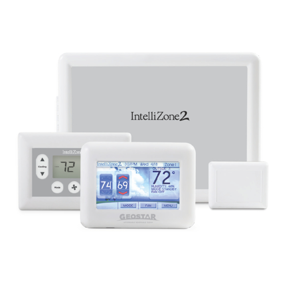
- Page 1 Comfort Zoning System Six Zone Capability Installation Information formation Damper Installation lation Thermostat Installation stallation Electrical Startup Procedures dures Wiring Schematic matic IM1578EW 07/20...
-
Page 3: Table Of Contents
IntelliZone2 with 5 Series SAH Air Handler ........ -
Page 4: Intellizone2 Components
IntelliZone2 MasterStat The IntelliZone2 MasterStat is the master control for the system and has all of the programming for operation. It is a 4.3 in. communicating color touch screen device that also functions as a zone thermostat for Zone 1. Optional remote sensor capability is also available. -
Page 5: General Installation Information
Safety Considerations Installation and Design Steps Installing and servicing heating and air conditioning The IntelliZone2 Comfort Zoning system is to be used equipment can be hazardous due to system electrical only with heat pumps/air handlers equipped with Aurora components. Only trained and qualifi ed service personnel AXB or AHB controls. -
Page 6: Damper Installation
INTELLIZONE2 INSTALLATION MANUAL Damper Installation Figure 2: Foam Taping Zone Damper Installing Rectangular Dampers in Metal Ductwork 3.75” Cut out dimensions A and B as shown in Figure 2 by using sheet metal snips. NOTE: Dimensions A and B are listed in the Dimensional Examples table. - Page 7 INTELLIZONE2 INSTALLATION MANUAL Damper Installation cont. Figure 5: Insulating Rectangular Metal Ductwork Insulating Rectangular Dampers in Metal Ductwork Duct wrap insulation Insulate ductwork as shown in Figure 5. All metal must be covered. Care must be taken not to obstruct the shaft from rotating when insulating.
- Page 8 INTELLIZONE2 INSTALLATION MANUAL Damper Installation cont. Figure 9: Taping Round Duct to Circular Damper Insulating Rectangular Ductboard/ Metal Sleeve Three screws sealed with duct tape or mastic Care must be taken not to obstruct the shaft from rotating Manual release button when insulating.
-
Page 9: Electrical Wiring
INTELLIZONE2 INSTALLATION MANUAL Electrical Wiring Wiring Damper Actuators All wiring must comply with local and state codes. Disconnect the power supply before beginning to wire to prevent electrical shock or equipment damage. All wiring should be run back to the control panel. Keep wires a minimum of 12 inches from any high voltage lines. - Page 10 Each Mount the transformer onto the side of the unit’s control IntelliZone2 3-wire damper requires 3.0VA at nominal box on the 5 Series and on the back of the control box on voltage and each 2-wire damper requires 7.0VA at nominal...
- Page 11 Fuse Black/White Yellow 5A Fuse Primary Leads Figure 17: IntelliZone2 to 5 or 7 Series Control Wiring Wiring IntelliZone2 to the Unit WARNING: All wiring must comply with local IntelliZone2 Relay Board and state codes. Disconnect the power supply before beginning to wire to prevent electrical 5 or 7 Series Heat Pump shock or equipment damage.
-
Page 12: Thermostat Installation
INTELLIZONE2 INSTALLATION MANUAL Thermostat Installation Locating the Thermostats The thermostats must be located in the room or zone that each controls. Locate a thermostat about five feet above the floor. Do not locate a thermostat where it may be exposed to direct sunlight, drafts or direct supply air. Do not place a thermostat on an outside wall. - Page 13 Strip the wires back 1/4 inch (longer TPCC32U01 strip lengths may cause shorts) and insert the thermostat IntelliZone2 wires into the IntelliZone2 connector as shown in Figure Relay Board 19. Tighten the screws to ensure tight connections. The thermostat has the same type connectors, requiring the same wiring.
-
Page 14: Intellizone2 Configuration
fi nger communication is OK. This will initiate communication over the IntelliZone2 logo in the upper left hand corner of between the IntelliZone2 system and the Aurora AXB/ABC. the Main screen for 5 sec. Select zone number and use the Config Aurora System up/down arrow▲▼... - Page 15 INTELLIZONE2 INSTALLATION MANUAL IntelliZone2 Confi guration cont. ZoneStats/SensorStats PCB Dual Fuel (Single Speed/Dual Capacity) - When Dual Fuel is selected for ‘Thermostat Type’ and a ‘W’ call is present TPCC32U01 operation will be as follows: IntelliZone2 Relay Board The temperature will be controlled by the MasterStat while other zones are ignored.
- Page 16 ‘Faster 1’ upstaging is inadequate. If the heat pump is already operating in first stage and a 45% or 70% zone The IntelliZone2 system allows separate staging options has had a heating or cooling demand for 15 continuous for cooling and heating. There are four options for each minutes then second stage will be activated.
- Page 17 50% for a 25% system demand. A common complaint is insufficient cooling when only one zone is calling for cooling. The IntelliZone2 will not initiate a “Y2” output to the unit until it senses a 50% total system demand (This is when the IntelliZone2 is set for normal upstaging).
- Page 18 As a bonus in this mode, upon a Y1 call, the IntelliZone2 may try to precondition the zone with return air from other zones already satisfied and, in some cases, can preclude the need for energizing the compressor.
- Page 19 MasterStat is selected. Equipment is automatically detected. Press by holding a finger over the IntelliZone2 logo for 5 sec. The the up and down arrows until the desired number of Configuration and Setup mode will appear automatically.
- Page 20 Installation or service. It should be noted that the MasterStat Z2TK troubleshooting harness can be useful here by allowing the temporary connection of the Status - Displays the outputs that the IntelliZone2 is MasterStat directly at the IntelliZone2 relay board for ease sending to the equipment.
- Page 21 Because IntelliZone2 ships standard with an outdoor sensor this option needs to be selected. NOTE: LAS on IntelliZone2 relay board = OAT This adjustment will vary the number of degrees, from the set point, before a call for heating or cooling is made.
- Page 22 1-9 and SuperBoost allows compressor speeds 10-12 if needed. This screen will Fault Status - Shows the last 10 IntelliZone2 system Faults allow the homeowner to turn the SuperBoost option ON (heat pump fault history is displayed at the heat pump on or OFF.
-
Page 23: Description Of Operation - Package Unit
Heating, Unit 3rd Stage IntelliZone2 Operation (Single/Dual Capacity Compressor and 5-Speed ECM) Upon a call (or calls) from the zones, the IntelliZone2 “weighs” each zone based upon two components: 1) the Operation as stated above with separate zone call levels of level of call (Y1, Y2, Y3) coming from the zone;... - Page 24 During the unit lockout mode, the appropriate Fault code delay, the dampers should be changed to the state required will be communicated to the IntelliZone2 MasterStat. by the next active call while the zone control should wait The blower will continue to operate on blower speed 1. If for the remainder of the short cycle delay before switching the collective zones translate into a >...
-
Page 25: Blower Data - Package Unit
---> 11 & 12 Selection NOTES: 1) Continuous Blower activated by G only call from IntelliZone2 (selection can be anywhere) 2) Aux Heat Airflow activated by Aux or Emergency heat call (selection ---> must be greater than high and allow proper airflow for the installed... - Page 26 INTELLIZONE2 INSTALLATION MANUAL Blower Data - Package Unit cont. In cooling a similar procedure occurs with the exception that compressor speed is limited to a maximum of speed 9. However compressor speed 10-12 is available for a short period of time and the resulting airflow during the ‘SuperBoost’...
- Page 27 CFM is controlled within ±5% up to the maximum ESP Max ESP includes allowance for wet coil and standard filter 7 Series - Variable Speed with Variable Speed ECM 7 Series Blower Speed Settings with IntelliZone2 Blower Level Percentages Model Max ESP...
- Page 28 The gray wire is not factory wired to the motor and is tied to the wire harness. This wire can be field connected and can be used with 3ht/2cl thermostats or IntelliZone2 to deliver the required air flow for the Y2 signal.
-
Page 29: Intellizone2 Cfm Design
Push the “Fan” button to the ON position on all by allowing the temporary connection of the MasterStat thermostats. (alternate method shown in the directly at the IntelliZone2 relay board for ease of note below) configuration or servicing. All dampers should start to open immediately. - Page 30 MasterStat by energized and the fan speed increases. Using the AID holding a finger on the IntelliZone2 logo for 5 seconds. The tool check the fan speed and compare to the Blower Configuration and Setup mode will appear automatically.
-
Page 31: Wiring Schematic
INTELLIZONE2 INSTALLATION MANUAL Wiring Schematic - Package Unit IntelliZone2 System Temporary IntelliZone2 Config or T-Shoot Relay Board Z2TK Kit Packaged Heat Pump F2 Relay AID Tool Board Fuse Microprocessor Aurora ABC and other 3A Fuse Components Note: Shorting a thermostat R/C input... -
Page 32: Intellizone2 Fault Codes
Zone 2 Sensor no Communications Use the Z2TK Harness to temporarily connect the IntelliZone2 MasterStat Damper Closed Z1-99 Zone 3 Sensor no Communications directly to the IntelliZone2 Relay Panel for ease of setup or troubleshooting. Damper Open Z1-100 Zone 4 Sensor no Communications Flashing... -
Page 33: Intellizone2 With 5 Series Sah Air Handler
INTELLIZONE2 INSTALLATION MANUAL IntelliZone2 with 5 Series SAH Air Handler... -
Page 34: Electrical Wiring
INTELLIZONE2 INSTALLATION MANUAL Electrical Wiring Transformer Mounting It is not recommended to mount the zone transformer in the 5 Series Outdoor Split compressor section and should be mounted to the air handler. For the 5 Series Indoor Split the zone transformer can be mounted to the air handler or in the compressor section. - Page 35 INTELLIZONE2 INSTALLATION MANUAL Electrical Wiring cont. For 208 volt operation, the red & blue transformer wires must be switched, use wire nuts only for connections to thermostat wire. Figure 20: Mounting and Wiring Transformer to Control Box (5 Series Indoor Split shown)
- Page 36 Harness supplied with IntelliZone2 then wire nut to stat wire Note: The harness supplied with IntelliZone2 is designed to plug into the Aurora AXB or AHB P7-Zone connection only. The IntelliZone2 cannot be connected to P7 on the ABC board.
-
Page 37: Description Of Operation With Split/Air Handler
The variable speed ECM motor allows 6 air flow levels with IntelliZone2 while the 5 Speed ECM will allow 4 air flow levels. Althought the 5 speed ECM works with the Cooling, Unit 1st stage... - Page 38 Once a mode is started, then that mode will continue IntelliZone2 operation may resume. until the thermostat(s) is/are satisfied for that mode or 20 minutes run time. After running for 20 minutes, the...
-
Page 39: Sah 5 Speed Ecm Blower Performance Data Option A
INTELLIZONE2 INSTALLATION MANUAL SAH 5 Speed ECM Blower Performance Data Option A Blower Performance 5 Speed ECM Control Option A Airflow (cfm) at External Static Pressure (in. wg) Motor Motor T’stat Blower Motor Model Speed Connection Size 0.05 0.10 0.15 0.20... - Page 40 INTELLIZONE2 INSTALLATION MANUAL SAH 5 Speed ECM Blower Performance Data Option A cont. Setting Blower Speed - 5-Speed ECM 5-Speed ECM Constant Torque Motors 5-Speed ECM blower motors have five (5) speeds of which The 5-Speed ECM is a 'Constant Torque' ECM motor and...
-
Page 41: Sah 5 Speed Ecm Blower Performance Data Option C
INTELLIZONE2 INSTALLATION MANUAL SAH Blower Performance Data Option C 5 Series - Single Speed Split with SAH Air Handler Variable Speed ECM Settings with IntelliZone2 Blower Level Percentages Split Motor HP MAX ESP Model Model 1050 1100 1200 1300 0.50... - Page 42 INTELLIZONE2 INSTALLATION MANUAL Blower Performance Data Option C cont. Setting Blower Speed - Variable Speed ECM Speed Setup - These screens allow the technician to select the “G”, low, high, and auxiliary heat blower speed for the ECM blower motor. Change the highlighted item using The ABC board’s Yellow Config LED will flash the current...
-
Page 43: Split Units Wiring Schematic
INTELLIZONE2 INSTALLATION MANUAL Wiring Schematic Split Units Temporary Config or IntelliZone2 T-Shoot Relay Board Z2TK Kit Split Heat Pump F2 Relay AID Tool Board Fuse Microprocessor Aurora ABC and other 3A Fuse Components Note: Shorting a thermostat R/C input will blow the ABC... - Page 44 INTELLIZONE2 INSTALLATION MANUAL Wiring Schematic cont. Split Units AXB and 5 Speed ECM To TB Y1 To TB Y2 To TB W1 To TB G F FG CC CCG REV REV FP1 FP1 FP2 FP2 LPS LPS HPS HPS F1-3A...
- Page 45 INTELLIZONE2 INSTALLATION MANUAL Wiring Schematic cont. Split Units AXB and 5 Speed ECM 3/31/17 208-230/60/1 Transformer Black Orange NOTE 1 Brown Blue Black 5 Speed Yellow Blk/Wh Blower Motor Green/Yellow Blue Grey SAH Air Handler Section Legend Factory Low voltage wiring...
- Page 46 INTELLIZONE2 INSTALLATION MANUAL Wiring Schematic cont. IntelliZone2 with Split ABC/AXB and SAH AHB and Variable Speed ECM (Preferred Way to Connect) Aurora Base Control (ABC) in Compressor Section RS485 NET RS485 EXP AHB™ PB2 in SAH Air handler Section Aurora AXB in...
-
Page 47: Intellizone2 With 7 Series Svh Air Handler
INTELLIZONE2 INSTALLATION MANUAL IntelliZone2 with 7 Series SVH Air Handler... -
Page 48: Electrical Wiring
INTELLIZONE2 INSTALLATION MANUAL Electrical Wiring Transformer Mounting For the 7 Series Indoor Split the zone transformer can be mounted to the air handler or in the compressor section. If the zone transformer is mounted to the air handler power will come from the PB located in the Air Handler electrical compartment. - Page 49 INTELLIZONE2 INSTALLATION MANUAL Electrical Wiring cont. For 208 volt operation, the red & blue transformer wires must be switched, use wire nuts only for connections to thermostat wire. Figure 20: Mounting and Wiring Transformer to Control Box (7 Series Indoor Split shown)
- Page 50 Harness supplied with IntelliZone2 then wire nut to stat wire Note: The harness supplied with IntelliZone2 is designed to plug into the Aurora AXB or AHB P7-Zone connection only. The IntelliZone2 cannot be connected to P7 on the ABC board.
-
Page 51: Description Of Operation With Split/Air Handler
Continuous Blower Upon a call (or calls) from the zones, the IntelliZone2 “weighs” each zone based upon two components: 1) the All dampers are open and the unit’s blower will be operated level of call (Y1, Y2, Y3) coming from the zone;... -
Page 52: Svh Blower Performance Data
INTELLIZONE2 INSTALLATION MANUAL SVH Blower Performance Data Variable Speed ECM Model Max ESP Speed 1 Speed 2 Speed 3 Speed 4 Speed 5 Speed 6 Speed 7 Speed 8 Speed 9 Speed 10 Speed 11 Speed 12 0.75 400 G... - Page 53 INTELLIZONE2 INSTALLATION MANUAL SVH Blower Performance Data cont. Setting Blower Speed - Variable Speed ECM Speed Setup - These screens allow the technician to select the “G”, low, high, and auxiliary heat blower speed for the ECM blower motor. Change the highlighted item using The ABC board’s Yellow Config LED will flash the current...
-
Page 54: Split Units Wiring Schematic
INTELLIZONE2 INSTALLATION MANUAL Wiring Schematic Split Units Temporary Config or IntelliZone2 T-Shoot Relay Board Z2TK Kit Split Heat Pump F2 Relay AID Tool Board Fuse Microprocessor Aurora ABC and other 3A Fuse Components Note: Shorting a thermostat R/C input will blow the ABC... - Page 55 INTELLIZONE2 INSTALLATION MANUAL Wiring Schematic cont. IntelliZone2 with Split ABC/AXB and SVH AHB and Variable Speed ECM(Preferred Way to Connect) Aurora Base Control (ABC) in Compressor Section RS485 NET RS485 EXP AHB™ PB2 in SAH Air handler Section Aurora AXB in...
-
Page 56: Revision Guide
INTELLIZONE2 INSTALLATION MANUAL Revision Guide Pages: Description: Date: 26 May 2020 Misc Added 7 Series Split and SVH Air Handler information 01 June 2019 14-24 Add zone naming, minor revisions to Configurations Misc. Updated Schematics, Added new Air Handler information 10 Mar 2017 Misc. - Page 57 INTELLIZONE2 INSTALLATION MANUAL Notes...
- Page 58 Six Zone Capability Document: Installation Manual *IM1578EW* ©2020 WaterFurnace International, Inc., 9000 Conservation Way, Fort Wayne, IN 46809-9794. WaterFurnace has a policy IM1578EW 07/20 of continual product research and development and reserves the right to change design and specifi cations without notice.
Need help?
Do you have a question about the IntelliZone2 and is the answer not in the manual?
Questions and answers
How to fix a Z1-99 error