
Related Manuals for WaterFurnace IntelliZone2


Summary of Contents for WaterFurnace IntelliZone2
- Page 1 Comfort Zoning System Four Zone Capability Designed for Use with Typical 24VAC Heat Pump Controllers Installation Information Damper Installation Thermostat Installation Electrical Startup Procedures Wiring Schematic IM1678EW 12/16...
-
Page 3: Table Of Contents
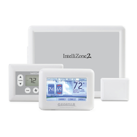
IntelliZone2 ● 24V Configuration ........ - Page 4 IntelliZone2 MasterStat The IntelliZone2 MasterStat is the master control for the system and has all of the programming for operation. It is a 4.3 in. communicating color touch screen device that also functions as a zone thermostat for Zone 1. Optional remote sensor capability is also available.
-
Page 5: General Installation Information
Zone Control Panels cartons if necessary. If any damage is noted, the carrier Locate the IntelliZone2 and IntelliZone2 ● 24V panels in an should make the proper notation on the delivery receipt, indoor area that has enough space for service personnel acknowledging the damage. -
Page 6: Damper Installation
INTELLIZONE2 ● 24V INSTALLATION MANUAL Damper Installation Figure 2: Foam Taping Zone Damper Installing Rectangular Dampers in Metal Ductwork 3.75” Cut out dimensions A and B as shown in Figure 2 by using sheet metal snips. NOTE: Dimensions A and B are listed in the Dimensional Examples table. - Page 7 INTELLIZONE2 ● 24V INSTALLATION MANUAL Damper Installation cont. Figure 5: Insulating Rectangular Metal Ductwork Insulating Rectangular Dampers in Metal Ductwork Duct wrap insulation Insulate ductwork as shown in Figure 5. All metal must be covered. Care must be taken not to obstruct the shaft from rotating when insulating.
- Page 8 INTELLIZONE2 ● 24V INSTALLATION MANUAL Damper Installation cont. Figure 8: Taping Round Duct to Circular Damper Insulating Rectangular Ductboard/ Metal Sleeve Three screws sealed with duct tape or mastic Care must be taken not to obstruct the shaft from rotating Manual release button when insulating.
-
Page 9: Electrical Wiring
INTELLIZONE2 ● 24V INSTALLATION MANUAL Electrical Wiring Wiring Damper Actuators All wiring must comply with local and state codes. Disconnect the power supply before beginning to wire to prevent electrical shock or equipment damage. All wiring should be run back to the control panel. Keep wires a minimum of 12 inches from any high voltage lines. - Page 10 INTELLIZONE2 ● 24V INSTALLATION MANUAL Electrical Wiring cont. WARNING: All wiring must comply with local Transformer Sizing and state codes. Disconnect the power supply Providing adequate transformer power (VA) to supply the before beginning to wire to prevent electrical system is an important requirement. Each 3-wire damper shock or equipment damage.
- Page 11 ‘L’ or ‘LO’ terminal on the heat pump control board. 3 – Field wire IntelliZone2 ● 24V - P4 to heat pump control board P1 as shown below. Figure 15: IntelliZone2 ● 24V to Heat Pump Control Wiring...
-
Page 12: Thermostat Installation
INTELLIZONE2 ● 24V INSTALLATION MANUAL Thermostat Installation Locating the Thermostats The thermostats must be located in the room or zone that each controls. Locate a thermostat about five feet above the floor. Do not locate a thermostat where it may be exposed to direct sunlight, drafts or direct supply air. - Page 13 Strip the wires back 1/4 inch (longer TPCC32U01 strip lengths may cause shorts) and insert the thermostat IntelliZone2 wires into the IntelliZone2 connector as shown in Figure Relay Board 17. Tighten the screws to ensure tight connections. The thermostat has the same type connectors, requiring the same wiring.
-
Page 14: Intellizone2 ● 24V Configuration
IntelliZone2 ● 24V is designed for non-communicating heat pump controls. Communication between the thermostats, IntelliZone2 relay board and IntelliZone2 ● 24V board is a 4-Wire Modbus protocol. The IntelliZone2 ● 24V board converts the Modbus communication into 24VAC signals which are delivered to the heat pump control. - Page 15 Staging Use the Z2TK Harness kit to temporarily connect the IntelliZone2 MasterStat directly to the IntelliZone2 Relay Panel for ease of setup or troubleshooting. Staging allows custom selection of staging for cooling and IntelliZone2 heating, independently.
- Page 16 If the heat pump is already The IntelliZone2 will not initiate a “Y2” output to the unit operating in second stage and a 45% or 70% zone has had...
- Page 17 It is a common assumption that if you have a house with it is really needed, thus saving money. As a bonus in this mode, upon a Y1 call, the IntelliZone2 ● 24V may try to two zones equally divided each zone should be set at an equal amount, usually 70%.
- Page 18 Remote Indoor Offset (if sensor is attached) Dual Fuel - Not Applicable - Operation is not available with IntelliZone2 ● 24V since it is a Outdoor Offset (if sensor is attached) Humidity Offset – This option allows calibration of the non communicating system humidity sensor.
- Page 19 Fault Status - Shows the last 10 IntelliZone2 ● 24V system Faults (heat pump fault history is displayed at the heat pump). The faults can be cleared or refreshed from this screen.
-
Page 20: Description Of Operation
Heating, Unit 3rd Stage (Single/Dual Capacity Compressor and 5-Speed ECM) Upon a call (or calls) from the zones, the IntelliZone2 ● Operation as stated above with separate zone call levels of 24V “weighs” each zone based upon two components: 1) YI, Y2, and W being translated into unit call 3rd stage (Y1, the level of call (Y1, Y2, Y3) coming from the zone;... - Page 21 INTELLIZONE2 ● 24V INSTALLATION MANUAL Description of Operation cont. Emergency Heat Emergency heat mode may be engaged by selecting at the MasterStat. All zone thermostat fault LED's begin to flash two quick flashes, followed by a pause, indicating that emergency heat mode has been activated. The temperature of the structure will be controlled by the zone 1 MasterStat while other zones are ignored.
-
Page 22: System Startup And Checkout
Push the “Fan” button to the ON position on all by allowing the temporary connection of the MasterStat thermostats. (alternate method shown in the directly at the IntelliZone2 relay board for ease of note below) configuration or servicing. All dampers should start to open immediately. - Page 23 In the following procedure, check for proper calls on the Status Screen. The setup and configuration mode should be entered at the MasterStat by holding a finger on the IntelliZone2 ● 24V logo for 5 seconds. The Configuration and Setup mode will appear automatically.
-
Page 24: Wiring Schematic
INTELLIZONE2 ● 24V INSTALLATION MANUAL Wiring Schematic IntelliZone2 Wiring System with Conversion Module (Orange) (Red) (Black) (Green) (White) Harness supplied with IntelliZone2. Cut off connector, strip wires and wire nut to conversion board. IntelliZone2 ZoneStat or SensorStat Zone 3 code shown Zone ID must be set for each Zone 2-4. - Page 25 INTELLIZONE2 ● 24V INSTALLATION MANUAL Wiring Schematic (Green) (Red) (Black) (White) 3-Wire Damper 2-Wire Damper...
-
Page 26: Intellizone2 ● 24V Fault Codes
IntelliZone2 ● 24V Fault Codes The following are IntelliZone2 ● 24V fault codes that can appear on the IntelliZone2 relay board LEDs and MasterStat. All control errors will be displayed on the MasterStat as “Exx” (xx equals error number) style and fault information can be... - Page 27 INTELLIZONE2 ● 24V INSTALLATION MANUAL Notes...
-
Page 28: Revision Guide
INTELLIZONE2 ● 24V INSTALLATION MANUAL Revision Guide Pages: Description: Date: Misc. Updated, Added TPCC32U01 and SensorStat 14 Dec 2016 First Published 12 Mar 2015... - Page 30 IntelliZone2 ● 24V Product: Type: Comfort Zoning System Size: Four Zone Capability Document: Installation Manual *IM1678EW* IM1678EW 12/16...
Need help?
Do you have a question about the IntelliZone2 and is the answer not in the manual?
Questions and answers