
Subscribe to Our Youtube Channel
Related Manuals for FunkTronic Major 4a


Summary of Contents for FunkTronic Major 4a
- Page 1 Major 4a English 3.4 No update at all! No update at all! See german version See german version Kompetent für Elektroniksysteme...
-
Page 2: Table Of Contents
Control Elements Major 4a General features Rearview Major 4a Sockets pinout Major 4a Connecting Major 4a (5a) --> Two-Way-Radio via multiwire Connecting Major 4a (5a) --> Line Interface LIM-AC Keypad layout in programming mode Menu structure 2-wire confi guration with FT630... -
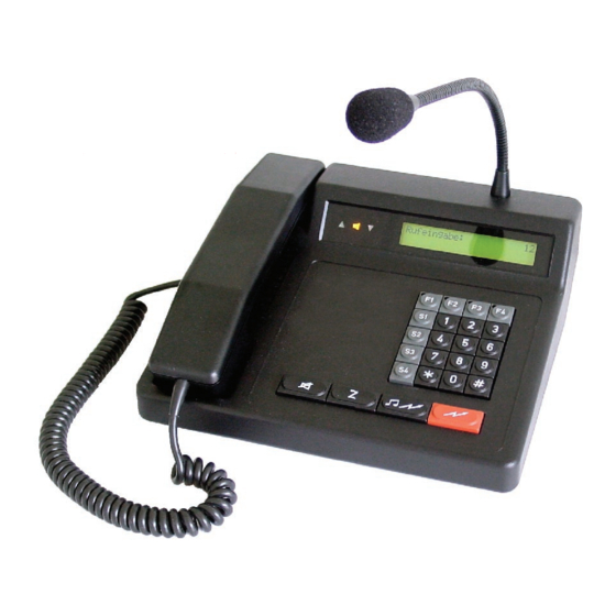
Page 3: Control Elements Major 4A
The Major 4a can be programmed via the serial interface or keypad. It is also possible to connect a printer or terminal on the serial interface. For printers with parallel interface an optional interface is available. -
Page 4: Rearview Major 4A
ST2A Headset 2 Digital outputs Serial interface RS232 PWR Power supply 12V, max. 1,5 A inside positive, outside ground Sockets pinout Major 4a Sockets pinout Major 4a All sockets shown from rear few. Pinout headset 1 + 2, Pinout Radio socket ST1,... -
Page 5: Connecting Major 4A (5A) --> Two-Way-Radio Via Multiwire
Connecting Major 4a (5a) --> Two-Way-Radio via multiwire All audio in/outputs of the Major 4a (5a) are equipped with transformers. No Pin’s are grounded in the Major 4a (5a); therefore a connection to ground must be made at the two-way-radio side, preferably by grounding PIN 1 and 8 to PIN 4. -
Page 6: Keypad Layout In Programming Mode
: F3 Next menu : F3 ” ” ” È È È Software: Major 4a V1.24 Register: Poti-Nr. (1-6): Date 23.09.04 1 = Input level - enter the register number 2 = Output level to be programmed - displayed for 3 seconds... - Page 7 Menu structure Continuation select number: simultaneously È “ “ “ Æ Æ Æ “ Adjust contrast Adjust contrast : F4 : F4 Set date/time Set date/time : F4 : F4 “ Transmit test tone Transmit test tone : F4 : F4 Æ...
- Page 8 Menu structure Continuation select number: simultaneously È “ “ “ Æ Æ Æ “ “ “ Æ Æ Æ Adjust clock Adjust clock : F4 : F4 Serial number Serial number : F4 : F4 “ Æ Next menu : F3 Next menu : F3 ”...
-
Page 9: 2-Wire Confi Guration With Ft630
Hardware confi guration 2/4-wire confi guration 2/4-wire confi guration The Major 4a (5a) is for use on 2- or 4-wire line. The confi guration for 2- or 4- wire is done in register 051/4. 2-wire confi guration with FT630 For remote control of radio over longer distance it is adviceable to use a 2-wire line with the FT630. -
Page 10: Software Confi Guration
Key F3 escapes without any changes. ” È Key F4 stores the displayed values. Register: All buttons of the Major 4a can be programmed EEPROM programmed with any function. Register 174 and 175 has to È be programmed with the appropriate values of the short call button (Z-Button). -
Page 11: Individual Programming Of The Buttons
(on or off). Digits 2 to 5 depend on the function programmed in the fi rst digit. Register: “ È Example for programming button - Funk Tronic Major 4a Programming „short press“: select number: select number: simultaneously Normally a long press of button is not È... -
Page 12: Loudspeaker Button Coding
5. Digit 9 = maximum loudness Register: The following steps are necessary to save the “ changes. È ” Funk Tronic Major 4a È select number: Register: EEPROM programmed È Register: Now press button once short and once long. After shortly pressing the display shows 1. -
Page 13: Encoder Prefi X
È EEPROM programming : F4 Next menu : F3 ” È Register: È Register: Code FFFFF ” È Register: EEPROM programmed È Register: “ È Funk Tronic Major 4a select number: m4a_eng (06.12.2005) - 13 - Kompetent für Elektroniksysteme... -
Page 14: Transmitting 6/7/8-Tone Sequences
Transmitting 6/7/8-tone Transmitting 6/7/8-tone Channel scanning function Channel scanning function Sequences The channel scanning function is activated if the waiting time in register 067/5 is programmed NOT To transmit an 8-tone sequence, the following to be zero. Zero deactivates this function. programming is necessary. -
Page 15: Reset To Factory Defaults
Reset to factory defaults The following steps resets the Major to factory defaults. Attention , all parameters will be reset without acknowledgement. select number: simultaneously È EEPROM programming : F4 Next menu : F3 ” È Register: È program EEPROM with default values select number: m4a_eng (06.12.2005) -
Page 16: Sample Confi Gurations Major 4A (5A)
Sample confi gurations Major 4a (5a) Sample confi gurations Major 4a (5a) The following situation shows the easiest way for remote radio control using a Major 4a (5a). A local 7-wire line (Audio, squelch, PTT) is required if remote channel select is not necessary. -
Page 17: Table Of Registers Major 4A
Table of registers Major 4a Decoder 10 Register Function Register Function Short dial 0 Short dial 1 Confi guration 1 for decoder 1 Short dial 2 Short dial 3 Digit -> ringing tone type Short dial 4 = no ringing tone... - Page 18 Register Function Register Function Confi guration 2 for decoder 1 Confi guration of loudspeaker timer Digit -> ID mode Digit = n * 100 sec = 5 tone sequence Digit = n * 10 sec = call sequence -> ID-code Digit = n * 1 sec dual sequence = ID-code ->...
- Page 19 Register Function Register Function Status Remote channel select Digit to 3 Digit 0 = no state Fixed digits remote tone sequence 1 = state with one digit in BCD code 2 = state with two digit Digit Channel register Status after switch on Channel after power on Digit 0= Reset channel...
- Page 20 Register Function Register Function Set-up for channel scanner General confi guration for decoder Digit=scan starts at channel Digit -> maximum length of EE = array reg. 070-074 remaining tones Digit = n * 500 msec Digit=scan to channel Digit = n * 50 msec Digit = n * 5 msec Digit ->...
- Page 21 Register Function Register Function Group call decoder Set-up 1 for FFSK-Emergency call Digit = Group call tone (Reg. 03x) F = Group call off Set-up 2 for FFSK-Emergency call Digit = external alarm (Reg. 03x) 0 = off 1-7 = external alarm 8-F = special call tones (call 1/2) Digit = external alarm Master password...
-
Page 22: Function Registers For Buttons
Function registers for buttons Register Function Function registers 130-177 Digit -> Function Function of 0 button, short press Function of 0 button, long press = none Function of 1 button, short press = transmit single tone Function of 1 button, long press = transmit call sequence Function of 2 button, short press = PTT... - Page 23 Function 2 --> transmit call sequence Function 3 --> PTT Digit -> type of call Digit -> choose microphone = entered call =PTT uses gooseneck = call back microphone = short dial = PTT uses headset = intercom microphone = PTT uses handset Digit ->...
- Page 24 Function 7 --> enter select number Digit = delete input = new input Digit -> function delete input = delete complete call = delete only last input Digit -> function new input 0-F = input = break Funtion 8 --> input status Digit = delete status = set status...
-
Page 25: Rs232 Cable For Flashing/Printing/Monitoring
Serial interface RS232 Serial interface RS232 Serial interface RS232 RS232 cable for flashing/printing/monitoring RS232 connector Major RS232 connector computer 25 and 9 pol connector uses the same pins, except GND PIN and the PINs for RxD and TxD are crossed. Pinout RS232 ST4 2 RxD RS232 (use PIN 3 for 9 PIN connector) -
Page 26: Release Notes
Release Notes 09. Nov. 2004 - manual version 2.0 english released 16. Nov. 2004 - new Hard/Software Major 4a released 17. Nov. 2004 - manual version 3.0 released, some changes due to new hard/software 25. Nov. 2004 - manual version 3.1 released, all reviewed 03.
Need help?
Do you have a question about the Major 4a and is the answer not in the manual?
Questions and answers