Table of Contents
Advertisement
Quick Links
Advertisement
Table of Contents

Subscribe to Our Youtube Channel
Related Manuals for FunkTronic Major 3 TRC


Summary of Contents for FunkTronic Major 3 TRC
- Page 1 Major 3 TRC English Version 1.0 Kompetent für Elektroniksysteme...
-
Page 2: Table Of Contents
Table of Contents Section Page Display and Control Elements General Operating Instructions Busy Indicator and carrier input Loudspeaker and indicator Call Handling Calling Radio Subscriber Short Call Numbers Group Call Transmitting a tone sequence with analog input Call from Radio Subscriber Input the status code Transmitting a call by pushing the PTT Transmitting a call by releasing the PTT... - Page 3 m3trc_eng (08.01.02) Service mode potentiometer Transmit levelling tones Adjustment Connector Technical Data - 3 - Kompetent für Elektroniksysteme...
-
Page 4: Display And Control Elements
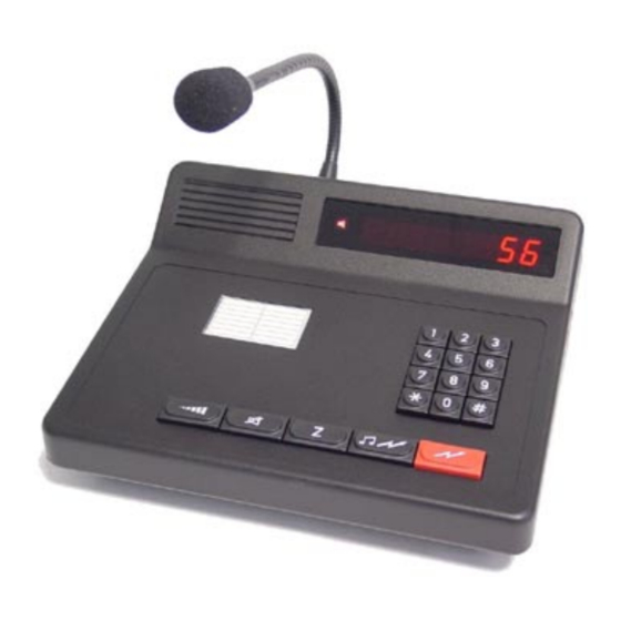
Display and Control Elements Rear view Major 3 1 - PTT Indicator 2 - Loudspeaker indicator 3 - Busy indicator 4 - PTT key 5 - Call button 6 - Short call button, status key 7 - Loudspeaker key 8 - Loudspeaker volume key 9 - Function key and channel selection 25-pol connector male 10 - Function key and ID-Code memory... -
Page 5: General Operating Instructions
(08.01.02) Major 3 TRC General Operating Instructions The Major 3 is controlled by a micro processor. It is used to control radio systems. To program the Major 3 you use easily the keyboard. There are two main versions of Major 3. One for use with 12 V DC main power and one with integrated 230 V AC power supply. -
Page 6: Call Handling
Register 050 loudspeaker mode and timer 1. position LS-Timer sec. * 100 2. position LS-Timer sec. * 10 3. position LS-Timer sec. * 1 4. position 0 = loudspeaker controlled mode 1 = loudspeaker always open Call Handling You can talk to the radio subscriber by pushing the PTT. After releasing the PTT button you will hear the radio subscriber through the loudspeaker. -
Page 7: Input The Status Code
m3trc_eng (08.01.02) Input the status code If you hold down the (Z) key for a moment you enter the status mode. Now you can enter a one or two digit status. Transmitting a call by pushing the PTT You can transmit a 5-tone or FFSK code by pushing the PTT. The code from register 015 is used. Register 053 3. -
Page 8: Receiving Of Calls
Receiving of calls The Major 3 has 10 decoders. They are coded in registers 020 to 029. If you don't need a decoder, put in an F on first position. You can also program different modes in the registers 030 to 039. The following modes are possible. -
Page 9: Conference Call Decoder
m3trc_eng (08.01.02) Conference Call Decoder The conference call decoder detects a tone of at least one second duration. After detection the loudspeaker is switched on, the loudspeaker lamp flashes, and the bell tone is activated. No acknowledgement is transmitted. The conference call tone frequency is coded at position 1 of register 044 with the corresponding digit of the tone system ('0' ... -
Page 10: Memory Updating
Memory updating Before an ID-code is accepted by the ID-code memory, the software checks if the same ID-code has already been stored in the memory. If the ID-code has already been stored and if the updating has not been activated, the ID-code is rejected. If the updating is switched on, the ID-code at the old position is deleted in order to be stored again at the first position. -
Page 11: Tone Table
m3trc_eng (08.01.02) Tone Table Tone ZVEI 1 CCIR ZVEI 2 ZVEI 3 2400 Hz 1981 Hz 2400 Hz 1981 Hz 2200 Hz 1060 Hz 1124 1060 Hz 1124 1160 1197 1160 1197 1060 Hz 1270 Hz 1275 Hz 1270 Hz 1275 Hz 1160 1400 Hz... -
Page 12: Pilot Tone And Dc Remote Control
Pilot tone and DC remote control The remote control is configured in position 3 and 4 at register 052. Register 052 3. position AC remote control 0 = no AC remote control 1 = AC remote control with pilot tone 3300 Hz 2 = AC remote control with pilot tone 3000 Hz 3 = AC remote control for Motorola TRC with guard tone 2100 Hz 4. -
Page 13: Ffsk Encoder
m3trc_eng (08.01.02) FFSK Encoder While the 5-tone and the FFSK decoder are ready for detection simultaneously, it has to be decided for call transmission whether a 5-tone or FFSK telegram shall be transmitted. The Major 3 derives this selection from the call number and automatically transmits the call in the correct call mode. -
Page 14: Rhomb
Rhomb The rhomb is programmed at position 5 of register 060. Application at disposal. FFSK Emergency Call If a FFSK telegram with status = emergency call is received, the loudspeaker is switched on, the loudspeaker lamp flashes, the emergency call ID-code is stored and flashes on the display. As long as an emergency call is displayed, the key pad is blocked (exception PTT). -
Page 15: Setup Mode
m3trc_eng (08.01.02) Setup Mode Setup Menu The setup menu is selected by pressing the (*) key and the (#) key simultaneously for one second. Now the message <SET> is shown on the left display and the cursor flashes at the input position of the right display. -
Page 16: Registers
EEPROM Addresses Register Coding for short call number 0 short call number 9 pre-coding of 5-tone encoder 5-tone sequence transmitted after activating analogue input 5-tone sequence transmitted after activating carrier input personally ID-code key tones standard acknowledgement decoder 1 decoder 10 setup for decoder 1 1. - Page 17 m3trc_eng (08.01.02) 1. position max. duration 1. tone, n * 5 msec * 100 2. position max. duration 1. tone, n * 5 msec * 10 3. position max. duration 1. tone, n * 5 msec * 1 4. position min.
- Page 18 setup for 5-tone sequence decoder, emergency call 1. position 2. position 3. position time in sec. for emergency output loudspeaker timeout 1. position n * sec * 100 2. position n * sec * 10 3. position n * sec * 1 4.
- Page 19 m3trc_eng (08.01.02) 5. position time slot between double sequence, n * 20 msec setup other functions 1. position setup status 0 = no status 1 = status one digit 2 = status two digit 2. position 3. position analogue input 0 = no action 1 = transmitting 5-tone sequence from register 011 if input low FFSK setup...
-
Page 20: Service Mode Analog Switches
Service mode analog switches During service work it can be necessary to switch a certain signal path. Since the processor controls all analog switches they can be switched by the service program. After selecting the service mode analog switches put in the number of the switch to control. Now the input is flashing and waiting for a 0 or a 1 (0=off, 1=on). - Page 21 - 6 dBm for 2-wire connection; for multi wire connection adjust to reach the nominal deviation of the radio - use poti no. 3 (CS3) for adjustment, 1000 Hz level tone is transmitted automatically Connector male, view from rear Major 3 TRC switch pin 1 switch pin 2 PTT, open collector, max.
- Page 22 Technical Data Major 3 Major 3 TRC Supply 230V version 230V AC +/- 10% 230V AC +/- 10% +12 V DC -10% +20% +12 V DC -10% +20% 12V version +12 V DC -10% +20% +12 V DC -10% +20% Current with max.
- Page 23 m3trc_eng (08.01.02) Change notices Change from 29.01.02 (Zier) / (Date of last version: 08.01.02): - page 4, picture M3 rear new - 23 - Kompetent für Elektroniksysteme...
Need help?
Do you have a question about the Major 3 TRC and is the answer not in the manual?
Questions and answers