Symantec NetBackup 5220 Hardware Troubleshooting Manual
Hide thumbs
Also See for NetBackup 5220:
- Troubleshooting manual (201 pages) ,
- Hardware installation manual (75 pages) ,
- Troubleshooting manual (48 pages)

Related Manuals for Symantec NetBackup 5220


Summary of Contents for Symantec NetBackup 5220
- Page 1 NetBackup 5220 and Symantec Storage Shelf™ Hardware Troubleshooting Guide Release 2.0...
- Page 2 Corporation or its affiliates in the U.S. and other countries. Other names may be trademarks of their respective owners. This Symantec product may contain third party software for which Symantec is required to provide attribution to the third party (“Third Party Programs”). Some of the Third Party Programs are available under open source or free software licenses.
- Page 3 The Technical Support group also creates content for our online Knowledge Base. The Technical Support group works collaboratively with the other functional areas within Symantec to answer your questions in a timely fashion. For example, the Technical Support group works with Product Engineering and Symantec Security Response to provide alerting services and virus definition updates.
- Page 4 Troubleshooting that was performed before contacting Symantec Recent software configuration changes and network changes Licensing and registration If your Symantec product requires registration or a license key, access our technical support Web page at the following URL: www.symantec.com/business/support/ Customer service Customer service information is available at the following URL: www.symantec.com/business/support/...
- Page 5 Europe, Middle-East, and Africa semea@symantec.com North America and Latin America supportsolutions@symantec.com...
-
Page 7: Table Of Contents
NetBackup 5220 RAID Support ................. 36 NetBackup 5220 Remote Management Module 3 (RMM3) ....... 43 NetBackup 5220 and Symantec Storage Shelf rack mounting ......43 NetBackup 5220 and Symantec Storage Shelf chassis covers ......43 Hot-swappable, Customer-replaceable units (CRUs) ............. 43 Non-Hot-swappable components (FRUs) ................. - Page 8 Chapter 4 Chapter 4 LED status indicators ............50 NetBackup 5220 LEDs ......................50 Mainboard LEDs ......................50 Control panel ........................51 2-Port 8Gb FC HBA ..................... 52 4-Port GE NIC ....................... 54 2-Port 10GE NIC ......................55 Symantec Storage Shelf LEDs ..................... 56 Disk module and device LEDs ..................
- Page 9 Possible Causes ......................84 Fault Diagnosis ......................84 Procedure ......................... 84 Chapter 6 Chapter 6 NetBackup 5220 hardware removal and replacement ... 93 Before you begin ........................93 Tools and supplies ......................93 Unpacking the NetBackup 5220..................94 Installing NetBackup 5220 guide rails ................94 Installing the NetBackup 5220 into a rack ...............
- Page 10 Tools and supplies ....................... 135 Unpacking the Symantec Storage Shelf ................135 Installing the Symantec Storage Shelf guide rails ............136 Installing the Symantec Storage Shelf into a rack ............136 Procedure ........................137 Symantec Storage Shelf cover/chassis ................137 Disk drives ..........................
- Page 11 Power Cord Usage Guidelines ..................156 Electromagnetic Compatibility Notices ................158 FCC Verification Statement (USA) ................. 158 ICES-003 (Canada) ...................... 158 CE Declaration of Conformity (Europe) ..............159 VCCI (Japan) ......................... 159 BSMI (Taiwan) ......................159 Regulated Specified Components ..................159 Chapter 11 Appendix C: Installation/Assembly Safety Instructions ....
-
Page 12: Figures
Figures NetBackup 5220 chassis (top, external view) ..................19 NetBackup 5220 components ......................... 23 NetBackup 5220 control panel LEDs ....................24 NetBackup 5220 mainboard components .................... 26 NetBackup 5220 configuration jumpers ....................29 NetBackup 5220 jumpers (actual) ......................30 NetBackup 5220 front ..........................31 NetBackup 5220 rear panel ........................ - Page 13 NetBackup 5220 on/off button ......................75 NetBackup 5220 power modules ......................77 System alarm/location indicator ......................83 Removing the NetBackup 5220 chassis cover ..................86 Chassis with cover removed ........................86 Chassis with air duct ..........................87 Chassis with DIMMs and DIMM slots ....................88 DIMM slots - detail ..........................
- Page 14 Fans, baffles, and bridge ......................... 132 Fan connectors ............................133 Symantec Storage Unit rack handles ....................137 Symantec Storage Shelf disk drives ....................138 Symantec Storage Shelf power supply modules ................139 NetBackup 5220 and Symantec Storage Shelf connection ............143...
-
Page 15: Tables
Tables NetBackup 5220 and Symantec Storage Shelf documentation set ..........17 NetBackup 5220 rear panel ports ......................34 NIC port LED indications ........................34 Midplane connectors ..........................35 Backplane connections (front) ........................ 35 Backplane connections (rear) ........................35 Hot-swappable components ........................44 Non-hot-swappable components ...................... -
Page 16: Chapter 1 About This Guide
About this guide Introducing this guide This document provides detailed instructions for troubleshooting hardware issues related to the NetBackup 5220 and Symantec Storage Shelf. A basic overview of the software is included. Product version The following table lists the product version related to this document. -
Page 17: Product Documentation
Product documentation NetBackup 5220 and Symantec Storage Shelf documents The six documents listed below are specific to the NetBackup 5220 appliance and the Symantec Storage Shelf. Additional information can be obtained in NetBackup 5200 (52xx) Series documentation, listed in the next section. - Page 18 NetBackup 5200 Series Command Reference Guide The NetBackup 5200 Series Command Reference Guide contains detailed information about the NetBackup appliance commands that you can run from the NetBackup appliance shell menu. Each command contains a brief description of the primary function of the command, a synopsis, and descriptions of each of the options listed in the synopsis.
-
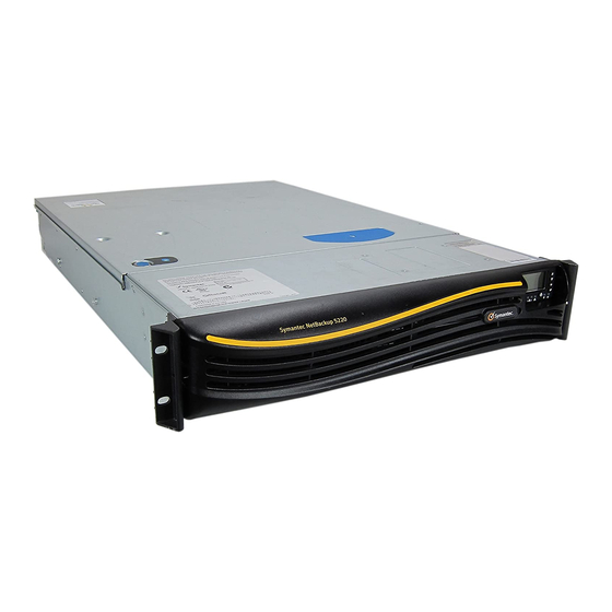
Page 19: Netbackup 5220 Chassis (Top, External View)
NetBackup 5220 and Symantec Storage Shelf description Chapter 2 NetBackup 5220 and Symantec Storage Shelf description This chapter describes the main features of the NetBackup 5220 and Symantec Storage Shelf, including physical descriptions and features. NetBackup 5220 chassis (top, external view) -
Page 20: Features
Features Dimensions 3.44 inches (87.30 mm) high 16.93 inches (430 mm) wide 27.75 inches (704.8 mm) deep 65 pounds (29.5 kg) - maximum chassis weight Server Board Server Board S5520UR Processor Intel ® Support for one or two Intel® Xeon® processors in FC-LGA 1366 Socket B package with up to 95 W Thermal Design Power (TDP) 4.8 GT/s, 5.86 GT/s and 6.4 GT/s Intel QuickPath Interconnect... - Page 21 Eight 2.5-inch hot-swap SAS hard drives Flex bay for two additional fixed 2.5-inch hard drives or 3.5- inch tape drive Intel Embedded Server RAID Technology II with SW RAID levels 0/1/10 ® Peripherals Slimline bay – not operational for the NetBackup 5220.
- Page 22 PCI riser card bracket Control Panel LEDs and status messages, control panel NIC1 (private network port) Activity NIC2 (service network port) Activity Power / Sleep System Status System Identification Hard Drive Activity Diagnostic LEDs ...
-
Page 23: Netbackup 5220 Components
Chapter 2 NetBackup 5220 and Symantec Storage Shelf description NetBackup 5220 components This section helps you identify the components of your device. You can also use the reference information provided on the inside of the chassis cover. NetBackup 5220 components... -
Page 24: Control Panel
Disk Carriers (qty 8, labeled 0 through 7 from left to right) Control panel The front right-hand side of the NetBackup 5220 contains a control panel, which shows system data messages. The On/Off switch for the device is located under the screen. - Page 25 Chapter 2 NetBackup 5220 and Symantec Storage Shelf description Letter Indications Hard disk Flashing green indicates hard disk activity (SAS, SATA). activity No light indicates no hard disk activity. NIC 2 activity Solid green light indicates a link between the system and the network.
-
Page 26: Mainboard
Mainboard NetBackup 5220 mainboard components... - Page 27 Chapter 2 NetBackup 5220 and Symantec Storage Shelf description Letter Component 280-pin Adaptive POST Code Diagnostic LEDs RMM3 Header Processor 1 Back Panel I/O Ports System Identification LED System Status LED Memory 1 Fan Header CPU 1 Fan Header Processor 1 DIMM slots (qty 6)
- Page 28 Letter Component SGPIO header I/O module mezzanine connector 2 I/O module mezzanine connector 1 Serial port B header...
-
Page 29: Configuration Jumpers
Chapter 2 NetBackup 5220 and Symantec Storage Shelf description Configuration jumpers NetBackup 5220 configuration jumpers... -
Page 30: Netbackup 5220 Jumpers (Actual)
If pins 2-3 are jumpered, the system can only boot (J1D4) from EFIbootable recovery media with the recovery BIOS image. The main system BIOS will not boot. These pins should be jumpered on 1-2 for normal system operation. NetBackup 5220 jumpers (actual) -
Page 31: Netbackup 5220 Front View
Chapter 2 NetBackup 5220 and Symantec Storage Shelf description NetBackup 5220 front view The NetBackup 5220 provides locations and hardware for installing 2.5-inch hard drives, a tape drive, CD-ROM drive, or DVD-ROM drive. The drives must be purchased separately. NetBackup 5220 front... -
Page 32: Netbackup 5220 Rear Panel
Slimline Optical Drive Bay The NetBackup 5220 includes a slimline optical drive bay, however the device does not have functionality for this type of drive at this time. Flex Bay The NetBackup 5220 provides a multi-purpose drive bay that can support either a tape drive or two additional fixed 2.5-inch hard drives. - Page 33 Chapter 2 NetBackup 5220 and Symantec Storage Shelf description Letter Description Low Profile PCI Express Add-in Card Slots (qty 2) Full-height PCI Add-in Card Slots (qty 3) Upper Power Supply Module Upper Power Receptacle Lower Power Receptacle Lower Power Supply Module...
-
Page 34: Netbackup 5220 Rear Panel Ports
Rear panel ports NetBackup 5220 Rear Panel Ports NetBackup 5220 rear panel ports Letter Name Model Function Serial port RJ45 Extends functions of the OS and third-party software. VGA (video) Connects to a computer monitor. port C, D USB 2.0 ports Connects mouse, keyboard, or similar devices. -
Page 35: Netbackup 5220 Sas Midplane
Chapter 2 NetBackup 5220 and Symantec Storage Shelf description NetBackup 5220 SAS midplane The midplane serves as the primary interface between the server board, hot-swap backplane, and control panel. The midplane is not field replaceable. Midplane connectors Optional RAID Cache Battery Backup Connector Midplane Power Connector ... -
Page 36: Netbackup 5220 Raid Support
The NetBackup 5220 can be used with the Symantec Storage Shelf to expand storage space. The NetBackup 5220 could also be used by itself. If the NetBackup 5220 is intended for use with at least one Symantec Storage Shelf, additional hardware is required. Extra parts include a RAID controller card, Battery Backup Unit (BBU) for the RAID card and six 4Gb DIMM cards to support the RAID card and additional storage. -
Page 37: Removing The Netbackup 5220 Chassis Cover
NetBackup 5220 and Symantec Storage Shelf description Removing the NetBackup 5220 chassis cover Remove the chassis cover completely. Chassis with cover removed Standing at the rear of the NetBackup 5220, place one hand on either side of the PCI Riser as shown above. -
Page 38: Chassis With Air Duct
Lift up with both hands. 10. Remove the Riser Card Assembly from the device. Chassis with air duct 11. Remove the plastic air duct. -
Page 39: Chassis With Riser Assembly And Air Duct Removed
Chapter 2 NetBackup 5220 and Symantec Storage Shelf description Chassis with riser assembly and air duct removed 12. Loosen the clips on both ends of each of the six empty DIMM sockets. 13. Remove any plastic spacers from the sockets. -
Page 40: Dimm Sockets
DIMM sockets Note: It does not matter into which sockets you place the DIMMs, they are interchangeable. 15. Position a DIMM above an empty socket. 16. Align the notch on the bottom edge of the socket with the key in the DIMM socket. 17. -
Page 41: Battery Screw Holes On Raid Controller Card
Chapter 2 NetBackup 5220 and Symantec Storage Shelf description Battery screw holes on RAID controller card 25. Fasten the battery to the card but do not over tighten or over torque the screws. 26. Remove the cover plate from Slot 5 of the riser card assembly. - Page 42 Rear of riser card assembly with slots 1-5 29. Replace the riser card assembly into the rear of the NetBackup 5220. 30. Align the three hooks in the PCI riser assembly with the matching slots at the back of the chassis.
-
Page 43: Netbackup 5220 Remote Management Module 3 (Rmm3)
Each left and right mounting rail for the Symantec Storage Shelf is shipped as a unit. The front and back of each rail slide apart a few inches to allow for precise fitting into the rack cabinet. -
Page 44: Hot-Swappable Components
Power supply #1 Rear panel, bottom left Device Symantec Storage Power supply #2 Rear panel, bottom right Device Symantec Storage SAS cable to NetBackup 5220 External device Device (qty 2) Symantec Storage AC power cord (qty 2) External device Device Notes/Conditions Remove disk drives in two stages;... - Page 45 Chapter 2 NetBackup 5220 and Symantec Storage Shelf description Device Component Component location Notes/Conditions Completely remove the disk module. Do not remove both power supplies at the same time. System power must be maintained. Do not remove both I/O modules at the same time.
-
Page 46: Non-Hot-Swappable Components (Frus)
The following components are field-replaceable units (FRUs). For the safety of personnel, equipment and data you must perform a full OS-driven shutdown of the equipment before working inside the chassis of the NetBackup 5220. Unplug all power sources and peripherals before removing the device from the rack. Review all applicable safety guidelines. -
Page 47: Chapter 3 General Fault Diagnosis
Chapter 3 General fault diagnosis Chapter 3 General fault diagnosis This chapter describes general principles of diagnosing faults. Basic principles Troubleshooting process Basic principles You must comply with the following principles during troubleshooting: Troubleshoot the peripheral devices first and then the internal components. Peripheral units include fibers, network cables, external devices such as computers or monitors, and power sockets. -
Page 48: Troubleshooting Processes
Troubleshooting processes This section describes general troubleshooting processes. Troubleshooting flowchart... -
Page 49: Check And Record Led Indicator Status
Read the control panel The control panel of the NetBackup 5220 is on the upper right side of the front panel. It provides basic system information via LEDs, plus detailed messages that you can scroll through to obtain insight into issues regarding the device. -
Page 50: Chapter 4 Led Status Indicators
Chapter 4 LED status indicators This chapter provides information on LED indicators that provide status information for the NetBackup 5220 and the Symantec Storage Shelf. NetBackup 5220 LEDs Mainboard LEDs NetBackup 5220 mainboard LEDs... -
Page 51: Control Panel
Letter Description POST Code Diagnostic LEDs System Identification LED Status LED Memory 1 Fan Fault LED CPU 1 Fan Fault LED CPU 1 DIMM Fault LEDs CPU 2 Fan Fault LED Memory 2 Fan Fault LED CPU 2 DIMM Fault LEDs 5V Standby LED Control panel... -
Page 52: 2-Port 8Gb Fc Hba
No light indicates system identification is not activated. 2-Port 8Gb FC HBA The 8Gb FC HBAs connects the NetBackup 5220 to other network and storage devices. It can provide two tape out FC ports. By using the tape out card (Fiber... -
Page 53: Netbackup 5220 2-Port 8Gb Fc Hba
Channel), data can be exported from the NetBackup 5220 to a tape library for offline storage. NetBackup 5220 2-port 8Gb FC HBA Note: Each port on the 8Gb FC HBA card shows three LEDs, labeled “8”, “4” and “2.” These numbers correspond to the rate of data transfer (8Gbit/s, 4Gbit/s or 2Gbit/s). -
Page 54: 4-Port Ge Nic
4-Port GE NIC The 4-port GE (Gigabit Ethernet) NIC provides four GE network ports for backup or replication. NetBackup 5220 4-port GE NIC 4-port GE NIC LED descriptions Type Color Status Description The link is normal and data is being... -
Page 55: 2-Port 10Ge Nic
2-Port 10GE NIC This section provides the physical view, features, and technical specifications for the NetBackup 5220 10GE (10 Gigabit Ethernet) NIC, which provides two 10GE network ports for backup. NetBackup 5220 2-port 10GE NIC 2-port 10GE NIC LED descriptions... -
Page 56: Symantec Storage Shelf Leds
Symantec Storage Shelf LEDs Disk module and device LEDs Symantec Storage Shelf front panel LEDs The front panel shows two different sets of LEDs; 2 LEDs each per disk module, for a total of 16 sets of LEDs ... -
Page 57: I/O Module Leds
Connect SAS IN ports on each storage shelf I/O module to the equivalent SAS ports in slot #5 of the PCI Riser Assembly in the rear of the NetBackup 5220. One I/O module is shown below, however each storage shelf includes two such... -
Page 58: I/O Module Leds
Starting up Not lit Note: When starting up the Symantec Storage Shelf, the primary I/O module (on the left side of the rear panel) starts up first. Its LED turns green a few seconds after the main startup. The LED of the secondary I/O module (on the... -
Page 59: Power Module Led
Power module LED The real panel Symantec Storage Shelf contains two side-by-side power modules. Each module includes two fans, a connector to a main AC power supply, on/off switch and a status indicator LED. Symantec Storage Shelf power module LED... -
Page 61: Chapter 5 Troubleshooting Scenarios
Chapter 5 Troubleshooting scenarios This chapter describes the troubleshooting process, fault analysis, and common methods for troubleshooting NetBackup 5220. Hardware fault types Hardware cannot be powered on or accessed Memory capacity has decreased Disk status LED is red ... -
Page 62: Hardware Cannot Be Powered On
Hardware cannot be powered on Two LEDs on the control panel on the front of the NetBackup 5220 show system and power status. If the system status indicator is off, the device is not powered on. NetBackup 5220 Status LEDs... -
Page 63: Possible Causes
NetBackup 5220 power module on/alarm LED Possible causes The AC power plug is not inserted properly. Main AC power is not supplied. Fault Diagnosis A flow chart to help diagnose power-on failure is planned for a future release of this document. -
Page 64: Memory Capacity Has Decreased
Cause 2: Power is not supplied Connect the NetBackup 5220 AC power cables to another external power source. Check the status of the power running/alarm indicator. If the power on/alarm indicator is flashing green, power on the device. If the system power indicator is on, the fault is removed. -
Page 65: Procedures
Procedures It is very important that proper air flow through the chassis is maintained at all times. DIMM slots are arranged for maximum air circulation and cooling. You must maintain the arrangement of DIMMs if you remove, install, or replace DIMMs. - Page 66 NetBackup 5220 and peripherals. Disconnect the NetBackup 5220 from power sources and all peripheral devices before removing hardware from the rack. Remove the NetBackup 5220 from the rack cabinet and place it on a level, ESD preventive surface. Remove the chassis cover.
- Page 67 This procedure assumes that you have verified that the correct number of DIMMs are installed in the correct slot configuration. Remove the NetBackup 5220 from the rack cabinet and place it on a level, ESD preventive surface. Remove the chassis cover.
- Page 68 DIMMs are functioning properly. However, you are still receiving data that suggests memory problems. Remove the NetBackup 5220 from the rack cabinet and place it on a level, ESD preventive surface.
-
Page 69: Disk Status Led Is Red
Contact technical support. Disk status LED is red The NetBackup 5220 contains eight disk bays. Each bay can hold one disk module, which includes one disk carrier and one disk drive. The carrier and its disk drive are labeled 0 to 7, from left to right. All drives are hot-swappable. Slot 7 is reserved as a spare. -
Page 70: Possible Causes
If the fault persists, check other components for further analyses. All disks cannot be scanned The NetBackup 5220 contains eight disk bays. Each bay can hold one disk module, which includes a disk carrier and a disk drive. This section describes how to troubleshoot the NetBackup 5220 when every... -
Page 71: Possible Causes
Possible Causes Cause 1: The disk module is not inserted properly Cause 2: The disk module is faulty Cause 3: The internal mini SAS cable is not inserted properly Fault Diagnosis A flow chart to help diagnose issues when some disks cannot be scanned is planned for a future release of this document. - Page 72 NetBackup 5220 and peripherals. Disconnect the NetBackup 5220 from power sources and all peripheral devices before removing hardware from the rack. Remove the NetBackup 5220 from the rack cabinet and place it on a level, ESD preventive surface. Remove the chassis cover.
-
Page 73: Fan On/Alarm Led Is Red Or Other Data Indicates Fan Problems
Fan On/Alarm LED is red or other data indicates fan problems The control panel on the front of the NetBackup 5220 displays fan status. If a problem is indicated you can inspect the six fan LEDs after removing the chassis cover. A green LED indicates normal operation. A red LED indicates a problem. -
Page 74: Symptoms
If the NetBackup 5220 is powered on, the chassis cover should not be removed for more than 5 minutes. Leaving the chassis open for a longer time may result in decreased air flow and increased component temperatures. Symptoms Control panel readout indicates fan problems Device management screens indicate fan problems. -
Page 75: Netbackup 5220 On/Off Button
Power off the entire system through the management interface. Verify that peripherals are shut down. Verify that the two power cables on the rear of the NetBackup 5220 are securely plugged into functioning main AC power sources such as wall outlets. - Page 76 Secure any loose connections. Make sure that no cables are twisted or crimped. Make sure that the entire fan module is seated securely in the chassis. Remove the blue fan baffle located between fans 3 and 6. Carefully lift the entire fan module (all six fans are assembled together).
-
Page 77: Power Module Problems
Power module problems There are two AC main power supply modules in the NetBackup 5220. You can see both modules on the rear panel, right-hand side, of the device. One module sits horizontally on top of the other module. Each module has an AC connector/socket, an LED, and two fans. -
Page 78: Possible Causes
You should replace any power module that is not functioning properly. If the indicator of one module is amber while the other module’s LED is green, NetBackup 5220 function is normal although data/operate is at risk if the second module fails. ... -
Page 79: Netbackup 5220 System-Induced Power-Off
Cause 2: The power supply is protected Unplug the power cords of all power supplies and contact technical support. Do not power-on the NetBackup 5220 if power supply issues are not resolved. Damage to the device may result. NetBackup 5220 system-induced power-off Definition: The terms “protection or protected”... -
Page 80: Procedure
Procedure Cause 1: AC input to the power supply module is incorrect Note: There are two power modules in each NetBackup 5220, each with an AC main power socket and an on/alarm indicator. These instructions assume that each power module will be tested. - Page 81 Standing at the front of the device, remove the screw on the top right-hand side of the chassis cover. If the NetBackup 5220 is powered on, the chassis cover should not be removed for more than 5 minutes. Leaving the chassis open for a longer time may result in decreased air flow and increased component temperatures.
-
Page 82: Alarm Information
Cooling device Device absent Investigate other possible problems Make sure the front and back of the NetBackup 5220 are clear of any obstructions so that air can flow easily from front to back. Verify that room temperature is within specifications. -
Page 83: System Alarm/Location Indicator Is On
System Alarm/Location indicator is on Symptoms The system alarm/location LED on the control panel on the front panel of the NetBackup 5220 is on. A system management alert/alarm is displayed. System alarm/location indicator TBD new photo – please help identify this LED... -
Page 84: Possible Causes
Verify that the equipment room meets temperature specifications for the NetBackup 5220 and Symantec Storage Shelf. Make sure the front and back of the NetBackup 5220 are clear of any obstructions so that air can flow easily from front to back. - Page 85 Cause 2: CPU-related alarm Alarms caused by CPU or installation faults require you to replace the chassis. For details about replacing the chassis of NetBackup 5220 contact technical support. Cause 3: Memory-related alarm Alarms caused by memory faults or installation problems require you to replace the memory (DIMMs) inside the chassis.
-
Page 86: Removing The Netbackup 5220 Chassis Cover
Remove the chassis cover completely. Chassis with cover removed Standing at the rear of the NetBackup 5220, place one hand on either side of the PCI Riser. 10. Lift up with both hands. 11. Remove the Riser Card Assembly from the chassis. -
Page 87: Chassis With Air Duct
After removing the chassis cover and the PCI Riser Assembly you can see the clear plastic air duct. It covers the two processors (CPUs) and the two sets of 6 DIMM slots. The duct helps maintain airflow through the device. Chassis with air duct 12. -
Page 88: Chassis With Dimms And Dimm Slots
Chassis with DIMMs and DIMM slots DIMM slots - detail... - Page 89 In order to maintain adequate thermal levels, you MUST install DIMMs and DIMM blanks in the appropriate DIMM slots. All blue DIMM slots in CPU 1 and CPU 2 must either have a DIMM or DIMM blank installed. You may store extra DIMM blanks in any of the unused CPU 1 DIMM slots.
-
Page 90: Power Supply Module Components
The power supply is hot-swappable only when two power supplies are installed into the NetBackup 5220. If only one power supply is installed, The power supply can be replaced if it fails or if one of the fans installed into the power supply fails. - Page 91 The fans in the power supply module are not removable. They remain inside the module as a complete unit. If there are problems with the fans, the entire power supply module must be removed and replaced. You must power the device down, turn off all peripheral devices connected to the system, turn off the system by pressing the power button, and unplug the AC power cord from the main AC power source before removing or replacing the power supply.
- Page 92 Verify that the air duct intake and output vents, at the front and rear of the chassis, respectively, are free of debris or blockage. After installing the cover, if the system alarm/location indicator turns off, the fault is resolved. If the fault persists, contact technical support.
-
Page 93: Chapter 6 Netbackup 5220 Hardware Removal And Replacement
NetBackup 5220 device, chassis, and components. Before you begin Before working with your NetBackup 5220, read and understand the safety information section in this manual. Also be sure you have reviewed the NetBackup 5220 Safety Guide for complete and detailed information regarding safety issues that apply to personnel, equipment, and environment. -
Page 94: Unpacking The Netbackup 5220
Chapter 6 NetBackup 5220 hardware removal and replacement Unpacking the NetBackup 5220 Unpacking the NetBackup 5220 The shipping box containing the NetBackup 5220 includes the following: NetBackup 5220 (qty 1) Network cables Left and right rack mounting rails (1 each) ... -
Page 95: Removing And Installing The Chassis Cover
Wear an ESD-preventive wrist strap and ESD-preventive gloves. Note: Locate the three heavy screws projecting from the left and right sides of the NetBackup 5220. These three screws fit into the three slots in the rail extenders. Using at least two people, lift the NetBackup 5220 and place it into the rail extenders. -
Page 96: Removing The Netbackup 5220 Chassis Cover
NetBackup 5220. Wear ESD preventive wrist straps. Carefully remove the NetBackup 5220 from the rack cabinet. Place it on a grounded, ESD protective surface. Remove the screw on the top, right-hand side of the chassis. Use the blue thumb grip on the top, left-hand side of the chassis to slide the cover towards the rear of the device. -
Page 97: Re-Installing The Netbackup 5220 Chassis Cover
Re-installing the NetBackup 5220 chassis cover Replace the chassis cover at the top rear of the NetBackup 5220 enclosure. Slide the cover from the rear of the device towards the front. Carefully line up both sides of the cover with the sides of the chassis itself. Do not allow warping or damage to the cover. -
Page 98: Removing The Chassis Cover
Unit (BBU) for the RAID card and six 4Gb DIMM cards to support the RAID card and additional storage. If the NetBackup 5220 and Symantec Storage Shelf are ordered at the same time, the RAID card and its accessories are installed into the NetBackup 5220 prior to shipment. -
Page 99: Removing The Pci Riser Assembly
Removing the NetBackup 5220 chassis cover Remove the chassis cover completely. Removing the PCI Riser Assembly Chassis with cover removed Standing at the rear of the NetBackup 5220, place one hand on either side of the PCI Riser as shown above. - Page 100 Chapter 6 NetBackup 5220 hardware removal and replacement Installing or replacing the RAID card and accessories 10. Lift up with both hands. 11. Remove the Riser Card Assembly from the device.
-
Page 101: Removing The Internal Air Duct
Chapter 6 NetBackup 5220 hardware removal and replacement Removing the internal air duct After removing the chassis cover and the PCI Riser Assembly you can see the clear plastic air duct. It covers the two processors (CPUs) and the two sets of 6 DIMM slots. -
Page 102: Adding Dimm (Memory)
Chapter 6 NetBackup 5220 hardware removal and replacement Installing or replacing the RAID card and accessories Chassis with riser assembly and air duct removed Adding DIMM (memory) Loosen the clips on both ends of each of the six empty DIMM sockets on the mainboard. -
Page 103: Dimm Sockets
Chapter 6 NetBackup 5220 hardware removal and replacement DIMM sockets Note: It does not matter into which sockets you place the DIMMs, they are interchangeable. 14. Position a DIMM above a socket. 15. Align the notch on the bottom edge of the socket with the key in the DIMM socket. -
Page 104: Installing The Battery Backup Unit (Bbu)
Chapter 6 NetBackup 5220 hardware removal and replacement Installing or replacing the RAID card and accessories Installing the Battery Backup Unit (BBU) Obtain the RAID controller card and Battery Backup Unit (BBU). Place the battery on the top of the RAID card. -
Page 105: Inserting The Raid Card Into The Pci Riser Assembly
Chapter 6 NetBackup 5220 hardware removal and replacement Inserting the RAID card into the PCI Riser Assembly Remove the cover plate from Slot 5 on the rear of the riser card assembly. Slot 5 on the rear of the PCI Riser Card Assembly Turn the riser card assembly upside down. - Page 106 Chapter 6 NetBackup 5220 hardware removal and replacement Installing or replacing the RAID card and accessories Rear of riser card assembly with slots 1-5 Replace the internal air duct into the chassis. Be sure it aligns correctly with the fan module, DIMM slots, CPUs, and side of the chassis.
- Page 107 Reinstall the single screw at the right front of the external chassis. Reinstall the NetBackup 5220 into the rack. Connect peripheral cables and the two main AC power cables. Turn on power to the device to restart.
-
Page 108: Installing Or Replacing Pci Add-In Cards
Installing or replacing PCI add-in cards Installing or replacing PCI add-in cards The NetBackup 5220 can be used with the Symantec Storage Shelf to expand storage space. The NetBackup 5220 could also be used by itself. If PCI add-in cards are required but not installed, obtain the necessary items from the customer and install them into the NetBackup 5220 chassis per the following procedure. -
Page 109: Removing The Netbackup 5220 Chassis Cover
Removing the NetBackup 5220 chassis cover Remove the chassis cover completely. Chassis with cover removed Standing at the rear of the NetBackup 5220, place one hand on either side of the PCI Riser as shown above. 10. Lift up with both hands. -
Page 110: Slots 1 To 4 On The Rear Of The Pci Riser Card Assembly
Chapter 6 NetBackup 5220 hardware removal and replacement Installing or replacing PCI add-in cards 12. Remove the cover plate from Slot 5 on the rear of the riser card assembly. Slots 1 to 4 on the rear of the PCI Riser Card Assembly 13. - Page 111 Chapter 6 NetBackup 5220 hardware removal and replacement To prevent the possibility of installing the replacement PCI add-in card on the wrong side of the PCI riser assembly, carefully replace one card at a time. 14. Install the PCI add-in cards into Slot 1 through 4 of the riser card assembly.
- Page 112 20. Connect any cables to the PCI add-in cards as needed. 21. Replace the chassis cover from the top rear of the NetBackup 5220 enclosure. 22. Slide the cover from the rear of the device towards the front.
-
Page 113: Removing And Re-Installing The Baffles
NetBackup 5220 hardware removal and replacement Removing and re-installing the baffles There are two baffles in the chassis of the NetBackup 5220. Both baffles are bright blue. They function to keep proper air flow through the chassis and across the internal components. -
Page 114: Removing The Fan Baffle
Chapter 6 NetBackup 5220 hardware removal and replacement Removing and re-installing the baffles Removing the fan baffle You may need to remove or loosen the fan baffle to remove the fan module. To remove the fan baffle: Remove the hook on the front of the baffle from the hole in the backplane board. -
Page 115: Review Of Netbackup 5220 Front Panel Disk Locations
Installing a Hot-swap SAS Hard Disk Drive You can install up to eight hot-swappable 1TB 2.5” SAS hard disk drive modules in the front panel of the NetBackup 5220. The disk drive and the carrier the contains it... -
Page 116: Removing A Hot-Swap Sas Hard Disk Drive
Pull out on the black lever and slide the module out from the device . With the black lever held in the fully open position, slide a new disk module into the NetBackup 5220 and push it in until you hear it click into place. - Page 117 Chapter 6 NetBackup 5220 hardware removal and replacement If you do not have a hard drive installed in the other drive bays, install the drive blank into the hard drive carrier. Install empty hard drive carriers into any remaining empty hard drive bays.
-
Page 118: Installing And Removing The I/O Expansion Module
Installing and removing the I/O expansion module Installing the I/O expansion module Be sure that the NetBackup 5220 has been properly powered off and that no programs or peripherals are running. If you connect these devices while programs are running, data loss may occur. -
Page 119: Removing The Netbackup 5220 Chassis Cover
Removing the NetBackup 5220 chassis cover Remove the chassis cover completely. Chassis with cover removed Standing at the rear of the NetBackup 5220, place one hand on either side of the PCI Riser as shown above. Lift up with both hands. -
Page 120: Chassis With Air Duct
Chapter 6 NetBackup 5220 hardware removal and replacement Installing and removing the I/O expansion module Chassis with air duct 11. Remove the plastic air duct. Notes: If you are installing an I/O expansion module that uses one socket, remove the filler panel from the slot that will connect the I/O module to the back panel and connector 1 on the mainboard. -
Page 121: Removing The I/O Expansion Module
Re-install the PCI riser assembly into the device. Removing the I/O Expansion Module Be sure that the NetBackup 5220 has been properly powered off and no programs or peripherals are running. If you disconnect devices while programs are running, data loss may occur. -
Page 122: Removing The Netbackup 5220 Chassis Cover
NetBackup 5220 Wear ESD preventive wrist straps. Carefully remove the NetBackup 5220 from the rack cabinet. Place it on a grounded, ESD protective surface. Remove the screw on the top, right-hand side of the chassis Use the thumb grip on the top, left-hand side of the chassis to slide the cover towards the rear of the device. -
Page 123: Chassis With Cover Removed
Chapter 6 NetBackup 5220 hardware removal and replacement Chassis with cover removed Standing at the rear of the NetBackup 5220, place one hand on either side of the PCI Riser as shown above. 10. Lift up with both hands. 11. Remove the Riser Card Assembly from the device. -
Page 124: Remote Management Module 3
The NetBackup 5220 can be used with the Symantec Storage Shelf to expand storage space. The NetBackup 5220 could also be used by itself. If the NetBackup 5220 is intended for use with at least one Symantec Storage Shelf, additional hardware is required. Extra parts include a RAID controller card, Battery Backup Unit (BBU) for the RAID card and six 4Gb DIMM cards to support the RAID card and additional storage. - Page 125 NetBackup 5220 Riser Card Assembly upon receipt of shipment. If a Symantec Storage Shelf is ordered later than the NetBackup 5220, a RAID Controller Card and accessories will need to be ordered and installed separately.
-
Page 126: Removing The Netbackup 5220 Chassis Cover
Removing the NetBackup 5220 chassis cover Remove the chassis cover completely. Chassis with cover removed Standing at the rear of the NetBackup 5220, place one hand on either side of the PCI Riser as shown above. Lift up with both hands. -
Page 127: Battery Screw Holes On Raid Controller Card
Chapter 6 NetBackup 5220 hardware removal and replacement 12. Remove the RAID card from the PCI Riser Card. 13. The Battery Backup Unit (BBU) fits onto the top of the RAID card. 14. Three screw hold the battery to the RAID card. -
Page 128: Replacing The Power Supply Modules
NetBackup 5220. Wear ESD preventive wrist straps. The NetBackup 5220 can be ordered with two power supply modules, which fit into the rear left-hand side of the chassis. Two power supply modules provide redundant power in case of failure of one of the modules. -
Page 129: Replacing A Fan Module
Power up the device through the OS. Replacing a fan module The six fans in the NetBackup 5220 can be removed as a single unit. It is not possible to replace individual fans. Be sure that the NetBackup 5220 has been properly powered off and no programs or peripherals are running. -
Page 130: Removing The Netbackup 5220 Chassis Cover
Remove the chassis cover completely. Chassis with cover removed Standing at the rear of the NetBackup 5220, place one hand on either side of the PCI Riser as shown above. Lift up with both hands and remove the Riser Card Assembly from the... -
Page 131: Chassis With Air Duct
Chapter 6 NetBackup 5220 hardware removal and replacement Chassis with air duct 10. Remove the plastic air duct. 11. Remove the blue air baffle from the left side of the chassis. 12. Loosen and lift the bridge by releasing the clip at its upper end. -
Page 132: Fans, Baffles, And Bridge
Chapter 6 NetBackup 5220 hardware removal and replacement Replacing a fan module Fans, baffles, and bridge 14. Carefully remove each of the six connectors between the fans and the mainboard. There is one connector for each fan. -
Page 133: Fan Connectors
26. Replace the chassis cover , making sure to secure the screw that holds the cover down. 27. Replace thc NetBackup 5220 into the rack cabinet. 28. Replace the AC main power cable and peripherals. 29. Power up the device through the OS. -
Page 134: Installing And Removing The Rack Handles
Installing and removing the rack handles Installing and removing the rack handles Rack handles are located on the left and right sides of the NetBackup 5220 front panel. The handles prevent the device from sliding out of the rack and allow attachment of the bezels. -
Page 135: Chapter 7 Symantec Storage Shelf Hardware Removal And Replacement
Symantec Storage Shelf device, components, and peripherals. Before you begin Before working with your Symantec Storage Shelf, read and understand the safety information section in this manual. Note: When you service the device, you must first power down the device through the OS. -
Page 136: Installing The Symantec Storage Shelf Guide Rails
Installing the Symantec Storage Shelf guide rails Each left and right mounting rail for the Symantec Storage Shelf is shipped as a unit. The front and back of each rail slide apart a few inches to allow for precise fitting into the rack cabinet. -
Page 137: Procedure
Symantec Storage Unit rack handles Symantec Storage Shelf cover/chassis The Symantec Storage Shelf chassis should not be opened. The only front panel components that can be removed and replaced are the disk drive modules. On the rear panel, the two I/O modules and two power supply modules can be hot-swapped. -
Page 138: Symantec Storage Shelf Disk Drives
Chapter 7 Symantec Storage Shelf hardware removal and replacement Disk drives Symantec Storage Shelf disk drives To remove and replace a disk drive module: Put on an ESD-preventive wrist strap. Press the disk module release button of the disk drive you want to remove. -
Page 139: Power Supply Modules
You may need to remove one or both of the power modules if there is failure. Be sure that the Symantec Storage Shelf has been properly powered off and no programs or peripherals are running. If you disconnect devices while programs are running, data loss may occur. -
Page 140: I/O Modules 1 And 2
I/O modules 1 and 2 There are two I/O modules in the Symantec Storage Shelf; one primary and one secondary module. Both modules are located in the rear of the storage shelf. I/O module #1 is on the left side of the device. I/O module #2 is on the right side of the device. -
Page 141: Cables
Chapter 7 Symantec Storage Shelf hardware removal and replacement Cables There are six ports on the rear panel of the Symantec Storage Shelf. Each I/O module has three ports; one RJ11 serial port and two SAS ports. Serial cable Communication between your storage shelf and the Command Line Interface (CLI) on your PC occurs via an RJ11 serial port on the rear panel of the storage shelf. -
Page 142: Power Cable
NetBackup 5220. Power cable Use the two power cords shipped with the Symantec Storage Shelf (1.5m (4.9 ft) power cords (qty 2). One power cord is provided for each of the two power supply modules in the storage shelf. -
Page 143: Sas Cable Connection To Netbackup 5220
5 on the rear panel of the NetBackup 5220. Repeat Steps 3 and 4 with the other SAS cable. NetBackup 5220 and Symantec Storage Shelf connection Note: On the rear panel of the Symantec Storage Shelf, the SAS OUT ports are not available for use at this time. -
Page 144: Chapter 8 Symantec Storage Shelf - Frequently Asked Questions
This chapter addresses various issues that technicians, engineers or customers may encounter. Sample questions (Q) and answers (A) are provided. Q: What kind of disk drives can I use with a Symantec Storage Shelf? A: Symantec supplies the Storage Shelf with 16 drives, with either 2 TB or 3 TB drives and a 3.5”... - Page 145 A: Yes. Disk drives are hot-swappable on the Symantec Storage Shelf. Q: Can the Symantec Storage Shelf run using just one power supply? A: Yes, it is possible to run the Symantec Storage Shelf on a single power supply. However, leaving one power supply off means there is no redundancy if the other power supply fails.
-
Page 146: Appendix A: Technical Reference
Appendix A: Technical Reference 750W single power supply input voltages The power supply must operate within all specified limits over the input voltage range. NetBackup 5220 power supply input voltages Parameter Rated Startup Power-off Max input Max rate input AC... -
Page 147: Environmental Specifications
Sound Power: 7.0 BA in an idle state at typical office ambient temperature (23 +/- 2°C) Electrostatic +/-12 KV except I/O port +/- 8 KV discharge (ESD) System Cooling NetBackup 5220: 2550 BTU/Hr Requirement Symantec Storage Shelf: 1270 BTU/Hr (BTU/Hr) -
Page 149: Appendix B: Regulatory And Certification Information
Appendix B: Regulatory and Certification Information WARNING: To ensure regulatory compliance, you must adhere to the assembly instructions in this guide to ensure and maintain compliance with existing product certifications and approvals. Use only the described, regulated components specified in this guide. Use of other products/components will void the UL listing and other regulatory approvals of the product and will most likely result in noncompliance with product regulations in the region(s) in which the product is sold. -
Page 150: Product Regulatory Compliance
Appendix B: Regulatory and Certification Information Product Regulatory Compliance Product Regulatory Compliance The NetBackup 5220 product, when correctly integrated per this guide, complies with the following safety and electromagnetic compatibility (EMC) regulations. Intended Application - This product was evaluated as Information Technology Equipment (ITE), which may be installed in offices, schools, computer rooms, and similar commercial type locations. -
Page 151: Product Ecology Compliance
Appendix B: Regulatory and Certification Information AS/NZS 3548 Emissions (Australia / New Zealand) BSMI CNS13438 Emissions (Taiwan) GOST R 29216-91 Emissions (Russia) GOST R 50628-95 Immunity (Russia) Belarus Certification (Belarus) Ukraine Certification (Ukraine) GB 9254 - CNCA Certification (China) ... -
Page 152: Product Regulatory Compliance Markings
Packaging & Product Recycling Marks Product Regulatory Compliance Markings The NetBackup 5220 product is provided with the following regulatory and safety markings. In the event there is no room for a marking(s) on the chassis, the information is provided in this guide. - Page 153 Appendix B: Regulatory and Certification Information FCC Marking (Class A) USA This device complies with Part 15 of the FCC Rules. Operation of this device is subject to the following two conditions: (1) This device may not cause harmful interference, and (2) This device must accept any interference received, including interference that may cause undesired operation.
- Page 154 Appendix B: Regulatory and Certification Information Product Regulatory Compliance Markings Belarus Safety Compliance Mark Belarus Waste of Electronic and Electrical Equipment Recycling Mark Europe China Restriction of Hazardous Substance Environmental Friendly Use Period Mark China China Recycling Mark China Recycling Marks International...
- Page 155 Appendix B: Regulatory and Certification Information Battery Perchlorate Warning Information California Perchlorate Material - Special handling may apply. www.dtsc.ca.gov/hazardouswaste/perchlorate This notice is required by California Code of Regulations, Title 22, Division 4.5, and Chapter 33: Best Management Practices for Perchlorate Materials. This product may include a battery which contains Perchlorate material.
-
Page 156: General Rack Mount Installation Guidelines
Appendix B: Regulatory and Certification Information General rack mount installation guidelines General rack mount installation guidelines Anchor the equipment rack: The equipment rack must be anchored to an unmovable support to prevent it from falling over when one or more servers are extended in front of the rack on slides. - Page 157 Appendix B: Regulatory and Certification Information Do not attempt to modify or use an AC power cord set that is not the exact type required. You must use a power cord set that meets the following criteria: Rating: In the U.S. and Canada, cords must be UL (Underwriters Laboratories, Inc.) Listed/CSA (Canadian Standards Organization) Certified type SJT, 18-3 AWG (American Wire Gauge).
-
Page 158: Electromagnetic Compatibility Notices
Appendix B: Regulatory and Certification Information Electromagnetic Compatibility Notices Electromagnetic Compatibility Notices FCC Verification Statement (USA) This device complies with Part 15 of the FCC Rules. Operation is subject to the following two conditions: (1) this device may not cause harmful interference, and (2) this device must accept any interference received, including interference that may cause undesired operation. -
Page 159: Ce Declaration Of Conformity (Europe)
Appendix B: Regulatory and Certification Information CE Declaration of Conformity (Europe) This product has been tested in accordance to, and complies with the Low Voltage Directive (73/23/EEC) and EMC Directive (89/336/EEC). The product has been marked with the CE Mark to illustrate its compliance. VCCI (Japan) This is a Class A product based on the standard of the Voluntary Control Council for Interference (VCCI) from Information Technology Equipment. -
Page 160: Appendix C: Installation/Assembly Safety Instructions
Appendix C: Installation/Assembly Safety Instructions English Appendix C: Installation/Assembly Safety Instructions English The power supply in this product contains no user-serviceable parts. There may be more than one supply in this product. Refer servicing only to qualified personnel. Do not attempt to modify or use the supplied AC power cord if it is not the exact type required. - Page 161 Appendix C: Installation/Assembly Safety Instructions After you have completed the six SAFETY steps above, you can remove the system covers: 1. Unlock and remove the padlock from the back of the system if a padlock has been installed. 2. Remove and save all screws from the covers. 3.
-
Page 162: Deutsch
Appendix C: Installation/Assembly Safety Instructions Deutsch Deutsch Benutzer können am Netzgerät dieses Produkts keine Reparaturen vornehmen. Das Produkt enthält möglicherweise mehrere Netzgeräte. Wartungsarbeiten müssen von qualifizierten Technikern ausgeführt werden. Versuchen Sie nicht, das mitgelieferte Netzkabel zu ändern oder zu verwenden, wenn es sich nicht genau um den erforderlichen Typhandelt. - Page 163 Appendix C: Installation/Assembly Safety Instructions 5. Tragen Sie ein geerdetes Antistatik Gelenkband, um elektrostatische Ladungen (ESD) über blanke Metallstellen bei der Handhabung der Komponenten zu vermeiden. 6. Schalten Sie das System niemals ohne ordnungsgemäß montiertes Gehäuse ein. Zur ordnungsgemäßen Kühlung und Lüftung muß die Gehäuseabdeckung immer wieder vor dem Einschalten installiert werden.
-
Page 164: Français
Appendix C: Installation/Assembly Safety Instructions Français Überspannungsschutzgerät verbunden sein; während eines elektrischen Sturms sollte keine Verbindung der Telekommunikationsleitungen mit dem Modem bestehen; mit einer geerdeten Wechselstromsteckdose ausgerüstet sein; über ausreichend Platz verfügen, um Zugang zu den Netzkabeln zu gewährleisten, da der Stromanschluß... - Page 165 Appendix C: Installation/Assembly Safety Instructions Une fois TOUTES les étapes précédentes accomplies, vous pouvez retirer les panneaux du système. Procédez comme suit: 1. Si un cadenas a été installé sur à l'arrière du système, déverrouillez-le et retirez-le. 2. Retirez toutes les vis des panneaux et mettez-les dans un endroit sûr. 3.
-
Page 166: Español
Appendix C: Installation/Assembly Safety Instructions Español Español El usuario debe abstenerse de manipular los componentes de la fuente de alimentación de este producto, cuya reparación debe dejarse exclusivamente en manos de personal técnico especializado. Puede que este producto disponga de más de una fuente de alimentación No intente modificar ni usar el cable de alimentación de corriente alterna, si no corresponde exactamente con el tipo requerido. - Page 167 Appendix C: Installation/Assembly Safety Instructions Para obtener un enfriamiento y un flujo de aire adecuados, reinstale siempre las tapas del chasis antes de poner en marcha el sistema. Si pone en funcionamiento el sistema sin las tapas bien colocadas puede dañar los componentes del sistema. Para instalar las tapas: 1.
-
Page 168: Italiano
Appendix C: Installation/Assembly Safety Instructions Italiano Italiano Rivolgersi ad un tecnico specializzato per la riparazione dei componenti dell'alimentazione di questo prodotto. È possibile che il prodotto disponga di più fonti di alimentazione. Non modificare o utilizzare il cavo di alimentazione in c.a. fornito dal produttore, se non corrisponde esattamente al tipo richiesto. - Page 169 Appendix C: Installation/Assembly Safety Instructions 2. Controllare che i cavi, dei supporti aggiuntivi ed altri componenti siano stati installati appropriatamente. 3. Attaccare le coperture al telaio con le viti tolte in precedenza e avvitarle strettamente. 4. Inserire e chiudere a chiave il lucchetto sul retro del sistema per impedire l'accesso non autorizzato al sistema.
Need help?
Do you have a question about the NetBackup 5220 and is the answer not in the manual?
Questions and answers