
Subscribe to Our Youtube Channel
Related Manuals for Wabtec NI 64


Summary of Contents for Wabtec NI 64
- Page 1 NI 64 Digital multimeter Handleiding Nieaf-Smitt is a brand name of Manual Wabtec NETHERLANDS...
- Page 2 Wabtec Netherlands B.V.. This also applies to accompanying drawings and diagrams. Due to a policy of continuous development Wabtec Netherlands B.V reserves the right to alter the equipment specification and description outlined in this document without prior notice and no part of this publication shall be deemed to be part of any contract for the equipment unless specifically referred to as an inclusion within such contract.
-
Page 3: Table Of Contents
Inhoud Veiligheid Omschrijving Symbolen Metingen 4.1 DC spanning meting 4.2 AC spanning meting 4.3 DC stroom meting 4.4 AC stroom meting 4.5 Weerstand meting 4.6 Continuity check 4.7 Diode test 4.8 Capaciteit meting 4.9 Frequentie/duty cycle meting Functies 5.1 Relatieve mode 5.2 Backlight 5.3 Hold 5.4 Auto power off... -
Page 4: Veiligheid
Veiligheid Neem de volgende voorzorgsmaatregelen door om ver-wonding en schade veroorzaakt door dit instrument of producten die erop zijn aangesloten te voorkomen. Om potentiële gevaren te voorkomen, mag u het instrument alleen op de gespecifi ceerde wijze gebruiken. LET OP: Deze meldingen duiden op omstandigheden of LET OP: Deze meldingen duiden op omstandigheden of handelingen die tot schade aan het instrument of aan andere handelingen die tot schade aan het instrument of aan andere... - Page 5 Dit symbool naast een of meerdere ingangen, geeft aan dat deze, bij normaal gebruik, gevaarlijke spanningen kunnen hebben. Voor maximale veiligheid, de meter en de meetsnoeren niet aanraken indien deze in gebruik zijn. Dit symbool geeft aan dat een apparaat volledig is beschermd door dubbele isolatie of versterkte isolatie.
- Page 6 Vervang de batterij zodra het ‘low battery’ symbool in het display Vervang de batterij zodra het ‘low battery’ symbool in het display verschijnt, om foutieve uitlezingen te voorkomen welke tot verschijnt, om foutieve uitlezingen te voorkomen welke tot elektrische schok en verwondingen kunnen leiden. elektrische schok en verwondingen kunnen leiden.
- Page 7 Ontlaad altijd condensatoren en filters en ontkoppel de voeding indien u weerstand of een diode test. Niet gebruiken met open behuizing. Zet om verwonding te voorkomen, het instrument nooit onder spanning of stroom als de behuizing van het instrument niet goed dichtgeschroefd is. Schakel altijd de voeding uit en verwijder de meetsnoeren voordat u de deksel opent ter vervanging van de zekering of batterijen.
-
Page 8: Omschrijving
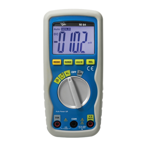
Multimeter beschrijving De NI 64 meet AC / DC spanning, AC / DC stroom, weerstand, capaciteit, frequentie (elektrisch & elektronisch), duty cycle, diodetest, isolatieweerstand en doorgang. Functies • Spanning AC/DC • Stroom AC/DC • Frequentie • Weerstand • Duty cycle Kenmerken •... - Page 9 Voorpaneel LCD display Functieschakelaar 10 A-ingang COM-ingang V Ω Hz % ingang MODE-toets RANGE-toets DATA HOLD-toets en achtergrondverlichting RELATIVE-toets Standaard en batterij compartiment bevinden zich aan de achterkant. www.nieaf-smitt.com...
-
Page 10: Symbolen
Symbolen •))) Continuiteit BATT Batterij status Diode test DATA HOLD Data vasthouden AUTO Automatisch bereik Wisselstroom of -spanning Gelijkstroom of -spanning www.nieaf-smitt.com... -
Page 11: Metingen
Metingen WAARSCHUWING: Hoge voltage circuits, AC en DC zijn beide erg WAARSCHUWING: Hoge voltage circuits, AC en DC zijn beide erg gevaarlijk en metingen moeten met grote zorg worden gevaarlijk en metingen moeten met grote zorg worden uitgevoerd. Draai ALTIJD de schakelaar op de OFF positie als de meter niet in gebruik is 2. -
Page 12: Ac Spanning Meting
AC spanning (frequentie, duty cycle) meting VOORZICHTIG: Meet geen AC spanning als er een motor in het circuit aan- of wordt uitgeschakeld. Grote spanning het circuit aan- of wordt uitgeschakeld. Grote spanning schommelingen kunnen mogelijk de meter beschadigen. schommelingen kunnen mogelijk de meter beschadigen. Plaats de functieschakelaar op de groene I positie Plaats het zwarte meetsnoer met banaan- stekker in de negatieve COM stekker... -
Page 13: Dc Stroom Meting
DC stroom meten Plaats het zwarte meetsnoer met banaanstekker in de negatieve COM stekker Plaats de functie schakelaar op de 10 A positie en plaatst het rode meetsnoer met banaanstekker in de 10 A stekker Druk de MODE knop in om de indicatie van “DC”... -
Page 14: Ac Stroom Meting
AC stroom (frequentie, duty cycle) meting Plaats het zwarte meetsnoer met banaanstekker in de negatieve COM stekker Plaats de functie schakelaar in op de 10 A positie en plaats het rode meetsnoer met banaanstekker in de 10 A stekker Druk de MODE knop in om de indicator van de “AC” weer te geven Verwijder de spanning op het circuit tijdens het testen, en meet nu de delen van het circuit waar een meting van wilt maken Verbind het zwarte uiteinde van de testsonde met de negatieve kant... -
Page 15: Weerstand Meting
Weerstand meting WAARSCHUWING: Om elektrische schok te vermijden, ontkoppel WAARSCHUWING: Om elektrische schok te vermijden, ontkoppel de voeding van de eenheid tijdens het testen en ontlaat alle de voeding van de eenheid tijdens het testen en ontlaat alle condensatoren alvorens een weerstandsmetingen uit te voeren. condensatoren alvorens een weerstandsmetingen uit te voeren. -
Page 16: Continuity Check
Continuiteit controle WAARSCHUWING: Om elektrische schok te vermijden, meet nooit WAARSCHUWING: Om elektrische schok te vermijden, meet nooit de continuïteit van circuits of draden wanneer er spanning op de continuïteit van circuits of draden wanneer er spanning op staat. Plaats de functieschakelaar op de positie Plaats het zwarte meetsnoer met banaanstekker in de negatieve COM stekker. -
Page 17: Diode Test
Diode test Plaats de functieschakelaar in de groene positie Plaats het zwarte meetsnoer met banaanstekker in de negatieve COM stekker Plaats het rode meetsnoer met banaanstekker in de positieve V stekker Gebruik de MODE knop om de indicator in het scherm weer te geven Verbind de uiteinden van de testsonde met de diode tijdens het onderzoeken. -
Page 18: Capaciteit Meting
Capaciteit meten WAARSCHUWING: Om elektrische schok te vermijden, ontkoppel WAARSCHUWING: Om elektrische schok te vermijden, ontkoppel de voeding van de eenheid tijdens het testen en ontlaat alle de voeding van de eenheid tijdens het testen en ontlaat alle condensatoren alvorens een capaciteitsmetingen uit te voeren. condensatoren alvorens een capaciteitsmetingen uit te voeren. -
Page 19: Frequentie/Duty Cycle Meting
Frequentie/duty cycle meting Plaats de functieschakelaar op de Hz/% positie Druk op de Mode knop in om de indicator “Hz” in het scherm weer te geven Plaats het zwarte meetsnoer met banaanstekker in de negatieve COM stekker Plaats het rode meetsnoer met banaanstekker in de positieve Hz stekker Verbind de uiteinden van de testsonde met het circuit tijdens het testen Weergave van de frequentie metingen op het scherm... -
Page 20: Functies
Functies RELATIVE modus De relatieve meet eigenschappen staat u toe om metingen met betrekking tot een opgeslagen referentiewaarde te maken. Een referentiespanning, stroom, enz. kan worden opgeslagen zodat de verdere metingen vergeleken kunnen worden met deze waarde. De getoonde waarde is het verschil tussen de referentiewaarde en de gemeten waarde. -
Page 21: Auto Power Off
Auto Power Off De meter zal automatische uitgeschakelen wanneer hij 15 min. buitengebruik is. Om de meter na een automatische uitschakeling in te schakelen, draai de MODE knop naar ON. Lege batterij indicatie Het pictogram zal in de lagere linkerhoek van het scherm verschijnen wanneer het batterijvoltage laag wordt. -
Page 22: Batterij Vervangen
HOUD DE METER SCHOON. Veeg nu en dan de meter af met een vochtige doek, gebruik geen chemische producten, schoonmakende oplosmiddelen, of afwasmiddel GEBRUIK ALLEEN VERSE BATTERIJEN VAN DE GEADVISEERDE GROOTTE EN HET TYPE. Verwijder oude of zwakke batterijen om beschadiging door lekkende batterijen te voorkomen ALS DE METER VOOR EEN LANGE TIJDSPANNE MOET WORDEN OPGESLA- GEN, zouden de batterijen verwijderd moeten worden om beschadiging... - Page 23 Ontkoppel de meetsnoeren van de meter Verwijder de batterij deksel en de batterijen Verwijder de vier schroeven die de achterkant vasthouden Verwijder voorzichtig de oude zekering en plaat een nieuwe in de zekeringhouder Gebruik altijd zekeringen van de juiste maat en waarde 10 A/600 V snel Plaats en bevestig de achterkant en de batterijdeksel) WAARSCHUWING: Om een elektrische schok te vermijden, stel WAARSCHUWING: Om een elektrische schok te vermijden, stel...
-
Page 24: Specificaties
Specificaties Functie Bereik Resolutiie Nauwkeurigheid DC spanning 400.0 mV 0.1 mV + (0.5 % + 2 d) (auto-ranging) 4.000 V 1 mV 40.00 V 10 mV + (1.2 % + 2 d) 400.0 V 100 mV 600 V + (1.5 % + 2 d) Invoer impedantie: 7.8 MΩ... - Page 25 Functie Bereik Resolutie Nauwkeurigheid AC stroom 10 A 10 mA + (3.0 % + 5 d) (auto-ranging) Overbelastingsbeveiliging: 10 / 600 V zekering. AC response: 50 Hz ...400 Hz Maximum invoer: 10 AAC rms bij 10 A bereik Functie Bereik Resolutie Nauwkeurigheid 400.0 Ω...
- Page 26 Functie Bereik Resolutie Nauwkeurigheid Frequentie 9.999 Hz 0.001 Hz + (1.5 % + 5 d) (auto-ranging) 99.99 Hz 0.01 Hz 999.9 Hz 0.1 Hz 9.999 kHz 1 Hz + (1.2 % + 3 d) 99.99 kHz 10 Hz 999.9 kHz 100 Hz 9.999 MHz 1 kHz...
- Page 27 EN61010-1, CAT III 1000 V & CAT IV 600 V; Verontreiniging Graad 2. Garantie Wabtec Netherlands B.V. geeft gedurende een periode van 12 maanden garantie op het meetsysteem. De garantieperiode gaat in op de dag dat de levering plaatsvindt. De aansprakelijkheid is vastgelegd in de leveringsvoorwaarden van het FME en www.nieaf-smitt.com...
- Page 28 Content Page Safety Description Symbols Operating Instructions 4.1 DC voltage measurement 4.2 AC voltage measurement 4.3 DC current measurement 4.4 AC current measurement 4.5 Resistance measurement 4.6 Continuity check 4.7 Diode test 4.8 Capacitance measurement 4.9 Frequency/duty cycle measurement Functions 5.1 Relative mode 5.2 Backlight 5.3 Hold...
-
Page 29: Safety
Safety Take the following precautions to avoid prevent injury or damage to this instrument or products that are connected. To avoid potential hazards, the instrument may only be used in the specifi ed manner. NOTE: Identifi es conditions and actions that could lead to damage NOTE: Identifi es conditions and actions that could lead to damage to the instument or other matter. - Page 30 This symbol indicates that a device is protected throughout by double insulation or reinforced insulation. General Use this multimeter only as specifi ed in this manual to prevent Use this multimeter only as specifi ed in this manual to prevent damage to the multimeter damage to the multimeter Always use proper terminals, switch position and range for...
- Page 31 To reduce the risk of fi re or electric shock do not expose this product to rain or moisture Safety instructions This meter has been designed for safe use, but must be operated with caution. The rules listed below must be carefully followed for safe operation. NEVER apply voltage or current to the meter that exceeds the specifi ed maximum.
- Page 32 Always discharge filter capacitors in power supplies and disconnect • the power when making resistance or diode tests • Always turn off the power and disconnect the test leads before opening the covers to replace the fuse or batteries • Never operate the meter unless the back cover and the battery and fuse covers are in place and fastened securely If the equipment is used in a manner not specified by the manufacturer, the...
-
Page 33: Description
Description The NI 64 multimeter measures AC/DC voltage, AC/DC current, resistance, capacitance, frequency (electrical & electronic), duty cycle, diode test, insulation test, and continuity. Functions • Voltage AC/DC • Current AC/DC • Frequency • Resistance • Duty cycle Features •... - Page 34 Front panel LCD display Function switch 10 A input jack COM input jack V Ω Hz % input jack MODE button RANGE button Backlight and Hold button REL button Tilt stand and battery compartment are on rear of unit. www.nieaf-smitt.com...
-
Page 35: Symbols
Symbols •))) Continuity BATT Battery status Diode test DATA HOLD Data hold AUTO Autorange Alternating current Direct current www.nieaf-smitt.com... -
Page 36: Operating Instructions
Operating instructions WARNING: Risk of electrocution. High-voltage circuits, both AC WARNING: Risk of electrocution. High-voltage circuits, both AC and DC, are very dangerous and should be measured with great and DC, are very dangerous and should be measured with great care. -
Page 37: Ac Voltage Measurement
AC voltage (frequency, duty cycle) measurement CAUTION: Do not measure AC voltages if a motor on the circuit is CAUTION: Do not measure AC voltages if a motor on the circuit is being switched ON or OFF. Large voltage surges may occur that being switched ON or OFF. -
Page 38: Dc Current Measurement
DC current measurement Insert black test lead banana plug into the negative COM jack. Set the function switch to the 10 A position and insert the red test lead banana plug into the 10 A jack Press the MODE button to indicate “DC” on the display Remove power from the circuit under test, then open up the circuit at the point where you wish to measure current... -
Page 39: Ac Current Measurement
AC current (frequency, duty cycle) measurement Insert black test lead banana plug into the negative COM jack Set the function switch to the 10 A position and insert the red test lead banana plug into the 10 A jack Press the MODE button to indicate “AC” on the display Remove power from the circuit under test, then open up the circuit at the point where you wish to measure current Touch the black test probe tip to the neutral side of the circuit... -
Page 40: Resistance Measurement
Resistance measurement WARNING: To avoid electric shock, disconnect power to the unit WARNING: To avoid electric shock, disconnect power to the unit under test and discharge all capacitors before taking any under test and discharge all capacitors before taking any resistance measurements. -
Page 41: Continuity Check
Continuity check WARNING: To avoid electric shock, never measure continuity on WARNING: To avoid electric shock, never measure continuity on circuits or wires that have voltage on them. circuits or wires that have voltage on them. Set the function switch to the green position Insert the black lead banana plug into the negative COM jack Insert the red test lead banana plug into the positive Ω... -
Page 42: Diode Test
Diode test Set the function switch to the green position Insert the black test lead banana plug into the negative COM jack and the red test lead banana plug into the positive V jack Press the MODE button to indicate and V on the display Touch the test probes to the diode under test Forward voltage will typically indicate 0.400 to 0.700 V... -
Page 43: Capacitance Measurement
Capacitance measurement WARNING: To avoid electric shock, disconnect power to the unit WARNING: To avoid electric shock, disconnect power to the unit under test and discharge all capacitors before taking any under test and discharge all capacitors before taking any capacitance measurements. -
Page 44: Frequency/Duty Cycle Measurement
Frequency/duty cycle measurement Set the rotary function switch to the green “Hz %” position Press the Hz/% button to indicate “Hz” in the display Insert the black lead banana plug into the negative COM jack and the red test lead banana plug into the positive Hz jack Touch the test probe tips to the circuit under test Read the frequency on the display Press the Hz/% button again to indicate “%”... -
Page 45: Functions
Functions RELATIVE mode The relative measurement feature allows you to make measurements relative to a stored reference value. A reference voltage, current, etc. can be stored and measurements made in comparison to that value. The displayed value is the diff erence between the reference value and the measured value. Perform the measurement as described in the operating instructions Press the REL button to store the reading in the display and the “REL”... -
Page 46: Low Battery
Low battery indication The icon will appear in the lower left conner of the display when the battery voltage becomes low. Replace the battery when this appears. Maintenance WARNING: To avoid electric shock, disconnect the test leads from WARNING: To avoid electric shock, disconnect the test leads from any source of voltage before removing the back cover or the any source of voltage before removing the back cover or the battery or fuse covers. -
Page 47: Battery Installation
Battery installation WARNING: To avoid electric shock, disconnect the test leads from WARNING: To avoid electric shock, disconnect the test leads from any source of voltage before removing the battery cover. any source of voltage before removing the battery cover. Turn power off and disconnect the test leads from the meter Open the rear battery cover by removing two screws (B) using a Phillips head screwdriver... -
Page 48: Specifications
Specifications Function Range Resolution Accuracy DC voltage 400.0 mV 0.1 mV + (0.5 % + 2 d) (auto-ranging) 4.000 V 1 mV 40.00 V 10 mV + (1.2 % + 2 d) 400.0 V 100 mV 600 V + (1.5 % + 2 d) Input Impedance: 7.8 MΩ... - Page 49 Function Range Resolution Accuracy 400.0 Ω 0.1 Ω Resistance (Ω) + (1.2 % + 4 d) (auto-ranging) 1 Ω 4.000 kΩ + (1.0 % + 2 d) 10 Ω 40.00 kΩ 100 Ω 400.0 kΩ + (1.2 % + 2 d) 4.000 MΩ...
- Page 50 Function Range Resolution Accuracy Duty cycle 0.1 % ~99.9 % 0.1 % + (1.2 % + 2 d) Pulse width: >100 us, <100 ms Frequency width: 5 Hz–150 kHz Sensitivity: <0.5 V RMS Overload protection: 1000 VDC or AC rms Function Test current Resolution...
- Page 51 2-031, 1 Edition (2003) Warranty Wabtec Netherlands B.V. guarantees the tester for a period of 12 months. The period of warranty will be effective at the day of delivery. The warranty clauses and the stipulations regarding liability in terms of delivery (FME and HE).
- Page 52 www.nieaf-smitt.com...
Need help?
Do you have a question about the NI 64 and is the answer not in the manual?
Questions and answers