Table of Contents
Advertisement
Quick Links
Advertisement
Table of Contents

Related Manuals for evoheat Solace Universal C-1200


Summary of Contents for evoheat Solace Universal C-1200
- Page 1 P a g e...
-
Page 2: Table Of Contents
P a g e Contents 1. Preface ..............................3 2. How It Works ............................. 4 3. Safety Instructions ............................. 5 4. Installation ..............................7 Installation Diagram ........................7 Installation Site ..........................8 Ducts Installation ........................... 9 Electrical Installation ........................10 Plumbing ............................11 Air-Cooled Condenser Installation ....................12 Pipe Installation ..........................13 5. -
Page 3: Preface
P a g e 1. Preface Thank you for choosing a Evo SOLACE UNIVERSAL Multi-functional Commercial Pool Dehumidifier & Ventilation unit. This is the operation manual for models C-250 to C-1800. Please read this manual carefully as it provides useful operation and maintenance information that will maximise the benefits your dehumidifier can offer. -
Page 4: How It Works
P a g e 2. How It Works MULTI FUNCTIONAL DEHUMIDIFIER REFRIGERANT SYSTEM SCHEMATIC The fan draws in warm, moist air from the pool enclosure. This air passes through the evaporator (dehumidification) coil and gives up heat energy to the refrigerant which is in a cool, liquid state. This exchange of energy causes the air temperature to fall below its dew point, resulting in moisture condensation on the evaporator coil. -
Page 5: Safety Instructions
P a g e 3. Safety Instructions Read the Safety Instructions carefully before operation. Incorrect handling could cause a serious hazard such as death, WARNING serious injury etc. with a high WARNING probability. No connection in the middle of power cord or extend Incorrect handling could cause a the power cord. - Page 6 P a g e WARNING Do not pull the power cord. Use the screwdriver to Do not apply an insecticide or flammable spray. It disconnect it. The core wire of the power cord may be may cause a fire or deformation of the cabinet. disconnected, and it may cause a fire.
-
Page 7: Installation
P a g e 4. Installation 4.1 Installation Diagram... -
Page 8: Installation Site
P a g e 4.2 Installation Site Select a suitable location for the unit, where the unit will not be subject to any damage. a) The unit must be mounted on a flat and level foundation capable of supporting the entire operating weight of the equipment. -
Page 9: Ducts Installation
P a g e 4.3 Ducts Installation... -
Page 10: Electrical Installation
| 10 P a g e 4.4 Electrical Installation 1.ELECTRICAL SAFETY It is important to ensure that all aspects of the installation comply with the latest I.E.E. Regulations. It is also important to ensure that any remote devices which terminate within the pool hall are of the type and voltage as specified in the latest I.E.E. -
Page 11: Plumbing
| 11 P a g e 4.5 Plumbing CONDENSATE DRAIN The condensate drip tray in the dehumidification unit collects the water removed by the dehumidification process, It is therefore necessary to ensure that the dehumidification unit is placed on a level plinth so that the condensate can run away and not overflow the edges of the drip tray inside the machine. -
Page 12: Air-Cooled Condenser Installation
| 12 P a g e 4.6 Air-Cooled Condenser Installation The most important consideration which must be considered when deciding upon the locations of air-cooled equipment is the provision for a supply of ambient air to the condenser, and removal of heated air from the condenser area. -
Page 13: Pipe Installation
| 13 P a g e 4.7 Pipe Installation Installation of the outdoor air-cooled condenser should only be done by a qualified refrigeration mechanic familiar with this type of work. Many service problems can be avoided by taking adequate precautions to provide an internally clean and dry system and by using procedures and materials that conform to established procedural standards. -
Page 14: Water Chemistry
| 14 P a g e 5 Water Chemistry 5.1 Pool Water Chemistry Water chemistry in swimming pools is critical for the health of the bathers and the condition of the enclosure and components. An enclosure with poor water chemistry has a noticeable “chlorine” smell, which is an indication of high chloramines in the air. -
Page 15: Start-Up
| 15 P a g e • If the unit is equipped with the auxiliary water-cooled air conditioning condenser, ensure that proper water flow and temperature are available. Check the water flow direction into and out of the unit. • Make sure that the fan belt(s) are tight and the fan scroll turns freely in the blower housing. •... -
Page 16: Operation
| 16 P a g e 7. Change the water temperature set point lower/higher than 27°C. This should cause the unit to change to air heating mode. 8. If the unit is equipped with an auxiliary air-cooled air conditioning condenser, change the air temperature set point lower/higher than current air temperature. -
Page 17: Run-Mode Menu
| 17 P a g e 7.2 Run-Mode Menu 1) AUTO Under this mode selection, the unit will run automatically by dehumidification and air heating, dehumidification and water heating, dehumidification and air cooling. The above screen contains basic information of the status and target set point status displays: Space Temp: Room (space) temperature in℃... - Page 18 | 18 P a g e 2) MANUAL WARNING Manual mode operation should only be performed by a qualified HVAC service technician. Improper use will cause system damage and possibly hazardous operation Under this mode selection, the unit will run on the selective mode The above screen contains basic information of the status and the selective running mode.
- Page 19 | 19 P a g e SpaceTempDiff: The temperature difference of room (space) temperature in℃ • SpaceHumidDiff: The humidity difference of room (space) relative humidity in % • • PoolTempDiff: The temperature difference of pool water temperature in℃ AuxPoolHeatDif: The temperature difference for auxiliary pool water heating in ℃ •...
-
Page 20: Alarms Menu
| 20 P a g e 7.3 Alarms Menu The alarms screen provides information on all the faults that have occurred in the dehumidifier. It can be used for troubleshooting by an experienced HVAC technician. The dehumidifier may stop when the fault occurs, Press the reset button after the fault has been eliminated to go back to normal operation 7.4 Sensors Off Set Menu The offset screen is to calibrate different sensors to a known standard. -
Page 21: Run-State Menu
| 21 P a g e 7.5 Run-state Menu The RUNSTATE screen contains the technical information of the status the dehumidifier 7.6 Curves Menu The CURVES screen is to display the value of Room (Space) temperature and Room (Space) Humidity. -
Page 22: On/Off Menu
| 22 P a g e 7.7 On/Off Menu ON/OFF screen is to turn on or turn off the dehumidifier The dehumidifier unit has numerous safety devices designed to protect the system from failures. Whenever a fault condition occurs, the alarm message will display on the screen. The dehumidifier may stop when the fault occurs, Press the reset button after the fault has been eliminated to go back to normal operation... -
Page 23: Alarm And Troubleshooting
| 23 P a g e 8 Alarm and Troubleshooting The alarm messages detected by the dehumidifier are displayed as below: ALARM MESSAGE CAUSE SOLUTION DEHUMIDIFIER 1# Tube temperature Sensor problem Change a new one Only the faulty sensor failure Sensor wire is loose Fasten the sensor wire system stops... - Page 24 | 24 P a g e 3# Compressor discharge Only the faulty temperature sensor Sensor problem Change a new one system stops failure Sensor wire is loose Fasten the sensor wire 4# Tube temperature Sensor problem Change a new one Only the faulty sensor failure system stops...
-
Page 25: Circuit Diagram
| 25 P a g e 9 Circuit Diagram C-1200, C-1500 THREE PHASE (3~N 50Hz) -
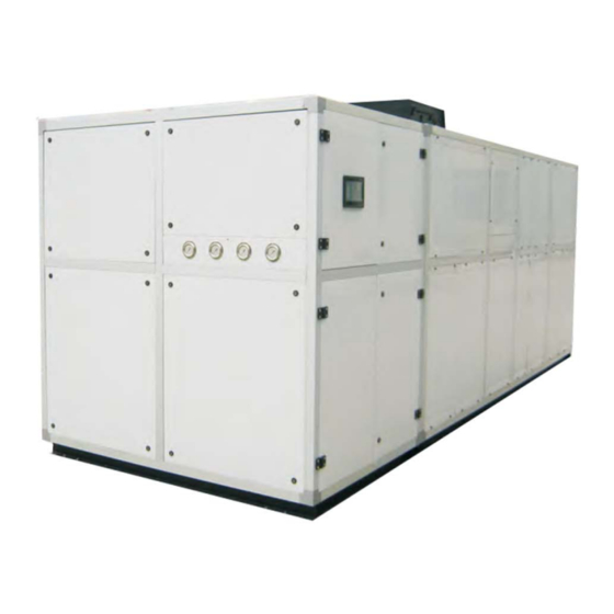
Page 26: Dimension And Parts
| 26 P a g e 10 Dimension and Parts 10.1 Description of Parts and Dimensions Dehumidifier (Indoor Unit) - Page 27 | 27 P a g e Air Cooled Condenser (Outdoor Unit)
-
Page 28: Maintenance
| 28 P a g e 11 Maintenance 11.1 Overview Periodic routine maintenance will promote extended equipment life. A simple check could result in noticing possible problems before they develop into major problems 11.2 Daily Maintenance Pool water chemistry is a part of daily maintenance and it is recommended to follow National Spa and Pool Institute standards. -
Page 29: Technical Specification
| 29 P a g e 12 Technical Specification Dehumidification System Specification C-1500 Dehumidification Capacity kg/hr (30°C,80%RH) Air heating capacity (30°C,80%RH) 291.4 Supply Air cbm/h 45000 External static pressure Compressor consumption power 73.8 Fan motor consumption power 15.2 Total consumption power Fresh air cbm/h 0~12000... -
Page 30: Guarantee Card
| 30 P a g e GUARANTEE CARD Dear Valued Customer, Thankyou for purchasing your Solace Universal Dehumidifier! We hope that you will be pleased in using the dehumidifier and find that it maintains a delicate balance of humidity control and manages air and water temperatures for maximum comfort at the lowest costs.
Need help?
Do you have a question about the Solace Universal C-1200 and is the answer not in the manual?
Questions and answers