Table of Contents
Advertisement
Available languages
Available languages
Quick Links
High Color‧Wide Screen‧
08
HMC
User-Friendly HMI Products
No.18, Xinglong Rd., Taoyuan City
Instrunction Sheet
(1) Preface
Thank you for purchasing DELTA's HMC series. This instruction sheet will be helpful in the installation, wiring and
inspection of Delta HMI. Before using the product, please read this instruction sheet to ensure correct use. You should
thoroughly understand all safety precautions before proceeding with the installation, wiring and operation. Place this
instruction sheet in a safe location for future reference. Please observe the following precautions:
Install the product in a clean and dry location free from corrosive and inflammable gases or liquids.
Ensure that all wiring instructions and recommendations are followed.
Ensure that HMI is correctly connected to a ground. The grounding method must comply with the electrical
standard of the country (Please refer to NFPA 70: National Electrical Code, 2005 Ed.).
Do not disassemble HMI, modify or remove wiring when power is applied to HMI.
Do not touch the power supply during operation. Otherwise, it may cause electric shock.
If you have any questions during operation, please contact our local distributors or Delta sales representatives.
The content of this instruction sheet may be revised without prior notice. Please consult our distributors or download the
most updated version at http://www.delta.com.tw/ia.
(2) Safety Precautions
Carefully note and observe the following safety precautions when receiving, inspecting, installing, operating, maintaining
and troubleshooting. The following words, DANGER, WARNING and STOP are used to mark safety precautions when
using the Delta's HMI product. Failure to observe these precautions may void the warranty!
Installation
Comply with quick start for installation. Otherwise it may cause equipment damage.
Do not install the product in a location that is outside the stated specification for the HMI. Failure to
observe this caution may result in electric shock, fire, or explosion.
Do not install the product in a location where temperatures will exceed specification for the HMI.
Failure to observe this caution may result in abnormal operation or damage the product.
Please note that this equipment has obtained EMC registration for commercial use. In the event that it
has been mistakenly sold or purchased, please exchange it for equipment certified for home use.
Do not use this product as an alarm device for disaster early warning that may result in personal injury,
equipment damage, or system emergency stop.
Wiring
Connect the ground terminals to a class-3 ground (Ground resistance should not exceed 100Ω).
Improper grounding may result in communication error, electric shock or fire.
Operation
The users should use Delta Screen Editor software to perform editing in Delta's HMI product. To
perform editing and confirming HMI programs without using Delta Screen Editor software in Delta's
HMI product may result in abnormal operation.
To prevent the personal injury and equipment damage, when designing HMI programs, please ensure
that a communication error occurred between Delta's HMI product and the connecting controller or
equipment will not result in system failure or malfunction.
Please be sure to backup the screen data and HMI programs in case they are lost, accidentally
deleted or worse.
Do not modify wiring during operation. Otherwise it may result in electric shock or personal injury.
Never use a hard or pointed object to hit or strike the screen as doing this may damage the screen and
let the screen has not respond at all, and then cause HMI to work abnormally.
Maintenance and Inspection
Do not touch any internal or exposed parts of the HMI as electrical shock may result.
Do not remove operation panel while power is on. Otherwise electrical shock may result.
Wait at least 10 minutes after power has been removed before touching any HMI terminals or
performing any wiring and/or inspection as an electrical charge may still remain in the HMI with
hazardous voltages even after power has been removed.
Turn the power off before changing backup battery and check system settings after finishing change.
(all data will be cleared after changing battery).
Be sure the ventilation holes are not obstructed during operation. Otherwise malfunction may result
due to bad ventilation or overheating troubles.
Wiring Method
Do not use a voltage that will exceed specification for the HMI. Failure to observe this caution may
result in electric shock or fire.
Remove the terminal block from the HMI before wiring.
Insert only one wire into one terminal on the terminal block.
If the wiring is in error, perform the wiring again with proper tools. Never use force to remove the
terminals or wires. Otherwise, it may result in malfunction or damage.
For the power line that forced to take out, ensure to check wiring again and restart.
Communication Wiring
Comply with communication wiring specification for wiring.
Wiring length should comply with the stated specification for the HMI.
Proper grounding to avoid bad communication quality.
To avoid noise and interference, the communication cable, all power cables, and motor power cable
should be placed in separate conduits.
(3) Model Explanation
(1)
(2)
(3)
(4)
(5)
33068, Taiwan
(6)
(7)
(8)
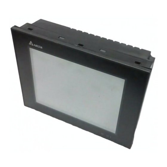
(4) Parts Names
HMC08-N500S52(Front View)
A
Power LED Indicator(
Operation LED Indicator(
B
/Alarm LED Indicator(
C
Touch Screen / Display
Note: The definition of the operation LED indicator (Blue) can be determined by the users freely.
HMC08-N500S52(Rear View)
A
HMC
08
-
N
5
00
S
5
2
(1)
(2)
(3)
(4)
(5)
(6)
(7)
(8)
Product Name
HMC: HMI with Controller
LCM Size
08: 8 inch TFT LCD
Type of Industries
N: General Purpose
Display specification
5: SVGA
Version
Type of Model
S: Standard ( built-in)
External Control Interface (Bus)
5: DMCNET
Controller Remote Unit interface
2: Specialized High-speed RS-422
A
B
)
Lights in green when HMI works normally.
Lights in blue: the communication is carried out /the data is
)
accessing. (Please refer to the "Note" below for explanation).
)
Lights in red: one of the alarms is on.
J
K
B
C
D
A
Power Input Terminal
COM3 (It is provided with two LED
indicators to indicate that HMI is in
B
Read
or Write status
communication process.)
COM2 (It is provided with two LED
indicators to indicate that HMI is in
C
Read
or Write status
communication process.)
D
COM1
E
USB Slave
(LAN)
F
Ethernet Interface
(5) Installation and Storage Conditions
The product should be kept in the shipping carton before installation. In order to retain the warranty coverage, the HMI
should be stored properly when it is not to be used for an extended period of time. Some storage suggestions are:
Store in a clean and dry location free from direct sunlight.
Store within an ambient temperature range of -20°C to +60°C (-4°F to 140°F).
Store within a relative humidity range of 10% to 90% and non-condensing.
Do not store the HMI in a place subjected to corrosive gases and liquids.
Correctly packaged and placed on a solid and durable surface.
Do not mount the HMI adjacent to heat-radiating elements or in direct sunlight.
Do not mount the HMI in a location subjected to corrosive gases, liquids, or airborne dust or metallic particles.
Do not mount the HMI in a location where temperatures and humidity will exceed specification.
Do not mount the HMI in a location where vibration and shock will exceed specification.
Do not mount the HMI in a location where it will be subjected to high levels of electromagnetic radiation.
C
(6) Installation and Wiring
Installation Notes:
Improper installation will result in malfunction and greatly reduce the life of the HMI. Be sure to follow the
guidelines in this quick start when installing the HMI.
In order to ensure the HMI being well ventilated, make sure that the ventilation holes are not obstructed and
must provide sufficient free space around HMI.
To ensure the panel is well protected, be sure to install a waterproof gasket into HMI.
For use on a flat surface of a Type 4X "Indoor Use Only" enclosure or equivalent.
The allowable thickness of the panel for mounting should be less than 5 mm.
Installation Method:
Step 1:
Ensure to put waterproof gasket into HMI and then
insert the HMI into the panel cutout.
Step 3:
Turn the screw with less than torque 0.7N.M to
avoid damage to plastic box.
Torque: 6.17lb-inch (0.7N-M)
I
H
G
Recommended wiring is in the table below:
Type
Wire Gauge (AWG)
F
Solid
28 ~ 12
Stranded
30 ~ 12
Be sure to perform wiring by referring to the following figure (power supply connector).
E
G
USB Host
H
Audio Output Interface
during the
Memory Card Slot / Battery
I
during the
Cover
J
DMCNET
K
Remote Module Interface
Step 2:
Ensure to insert fasteners into the HMI's
insertion slots and turn the screw till screws
touch panel cutout.
Step 4:
Keep at least 60mm distance from rear of HMI
product to the wall, installation surface or the
other controllers for heat dissipation.
Units: mm
Stripped length
Torque
7 ~ 8 mm
5 kg-cm(4.3 lb-in)
7 ~ 8 mm
5 kg-cm(4.3 lb-in)
Advertisement
Table of Contents

Subscribe to Our Youtube Channel
Related Manuals for Delta HMC08


Summary of Contents for Delta HMC08
- Page 1 (4) Parts Names inspection of Delta HMI. Before using the product, please read this instruction sheet to ensure correct use. You should The product should be kept in the shipping carton before installation. In order to retain the warranty coverage, the HMI thoroughly understand all safety precautions before proceeding with the installation, wiring and operation.
- Page 2 1.5 ~2 times the value of the power consumption. RXD- Users can download the Screen Editor V2.00, the program editor of Delta HMI product and the user manual via the Note1: Blank = No Connection. following link: http://www.delta.com.tw/ia.
- Page 3 Harici Kontrol Arabirimi (Bus) 5: DMCNET DELTA’nın HMC serisi operatör panellerini seçtiğiniz için teşekkürler. Bu bilgi dokümanı Delta HMI kurulum, bağlantı, Kurulum yapılana kadar ürün orjinal kutusu içinde muhafaza edilmelidir. Ürünün garanti kapsamının devamı için, ürün bakım ve kontrolünde kullanıcıya yardımcı olacaktır. Doğru kullanım için ürünü kullanmadan önce bu dokümanı mutlaka Uzak Birim Kontrolör Arabirimi...
- Page 4 Güç tüketimi HMI ünitesinin hiç bir cihaza bağlı olmadan boş olarak tükettiği gücü gösterir. Normal çalışmada HMI’nın boş iken tükettiği gücün 1.5 veya 2 katı güç verebilen besleme kaynağı kullanılması tavsiye edilir. (10) Özellikler Aşağıdaki linkten Delta HMI ürünleri için kullanım klavuzu ve Screen Editor programını indirebilirsiniz: RXD- http://www.delta.com.tw/ia.
- Page 5 控制器 Remote Unit 介面 2: 專用高速 RS-422 避免儲存於含有腐蝕性氣、液體之環境中。 最好適當包裝存放在架子或台面。 (1) 一般注意事項 (4) 各部位說明 本產品適合的安裝環境包括有:無發高熱裝置之場所﹔無水滴、蒸氣、灰塵及油性灰塵之場所﹔無腐蝕、易燃性 感謝您使用本產品,本人機介面安裝說明書提供 HMC 系列人機介面的相關資訊。在使用之前,請您仔細詳讀本說明書以 HMC08-N500S52(正面) 之氣、液體之場所﹔無漂浮性的塵埃及金屬微粒之場所﹔堅固無振動、無電磁雜訊干擾之場所。 確保使用上的正確。此外,請妥善將其放置在明顯的地點以便隨時查閱。下列事項在您尚未讀完本說明書前,請務必遵守: 安裝的環境必須沒有水氣,腐蝕性氣體及可燃性氣體。 (6) 安裝方向與配線 接線時,請依接線圖說明施工。 注意事項: 接地工程必須確實實施,接地時須遵照國家現行相關電工法規之規定施行(請參考 NFPA 70: National Electrical Code, 2005 Ed.) 。...
- Page 6 註 2:當 COM2 使用 RS-232 流量控制(RTS、CTS 腳位)時,COM3 則無法使用。 型號 HMC08-N500S52 確保人機工作正常。 註 3:當 COM2 使用 RS-422 流量控制時,其流量控制腳位請參考 COM3 MODE2 括號內的腳位定義。 面板種類 8”TFT LCD(65536 色) 6) HMC 系列編輯軟體 DOPSoft 系列及其使用操作手冊,可由台達網站下載取得,網址為 http://www.delta.com.tw/ia。 COM3 定義 顯 解析度 800 x 600 pixels 7) 本人機介面安裝手冊內所記載之規格若有變更,本公司恕不另行通知。當內容規格有所修正時,請洽詢代理商或至台 示...
- Page 7 2: 专用高速 RS-422 (1) 一般注意事项 避免储存于含有腐蚀性气、液体的环境中。 感谢您使用本产品,本人机界面安装说明书提供 HMC 系列人机界面的相关资讯。在使用之前,请您仔细详读本说明书以 最好适当包装存放在架子或台面。 (4) 各部位说明 确保使用上的正确。此外,请妥善将其放置在明显的地点以便随时查阅。下列事项在您尚未读完本说明书前,请务必遵守: 本产品适合的安装环境包括有:无发高热装置的场所﹔无水滴、蒸气、灰尘及油性灰尘的场所﹔无腐蚀、易燃性 安装的环境必须没有水气,腐蚀性气体及可燃性气体。 的气、液体的场所﹔无漂浮性的尘埃及金属微粒的场所﹔坚固无振动、无电磁噪音干扰的场所。 HMC08-N500S52(正面) 接线时,请依接线图说明施工。 接地工程必须确实实施,接地时须遵照国家现行相关电工法规的规定施行(请参考 NFPA 70: National Electrical (6) 安装方向与配线 Code, 2005 Ed.) 。 注意事项: 在通电时,请勿拆解人机界面或更改配线。 安装方向必须依规定,否则会造成故障。 在通电运作时,请勿接触电源处,以免触电。 ...
- Page 8 注 2:当 COM2 使用 RS-232 流量控制(RTS、CTS 脚位)时,COM3 则无法使用。 型号 HMC08-N500S52 确保人机工作正常。 注 3:当 COM2 使用 RS-422 流量控制时,其流量控制脚位请参考 COM3 MODE2 括号内的脚位定义。 面板种类 8”TFT LCD(65536 色) 6) HMC 系列编辑软件 DOPSoft 系列及其使用操作手册,可由台达网站下载取得,网址为 http://www.delta.com.tw/ia。 COM3 定义 显 解析度 800 x 600 pixels 7) 本人机界面安装手册内所记载之规格若有变更,本公司恕不另行通知。当内容规格有所修正时,请咨询代理商或至台 示...
Need help?
Do you have a question about the HMC08 and is the answer not in the manual?
Questions and answers