
Related Manuals for SEGA ENTERPRISES Confidential Mission


Summary of Contents for SEGA ENTERPRISES Confidential Mission
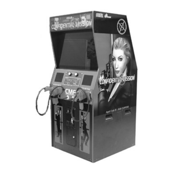
- Page 1 1ST PRINTING JAN 01 U/R Type Owner’s Manual SEGA ENTERPRISES, INC. USA MANUAL NO. 420-6602-01...
- Page 2 Warranty Your new Sega Product is covered for a period of 90 days from the date of shipment. This certifies that the Printed Circuit Boards, Power Supplies and Monitor are to be free of defects in workman- ship or materials under normal operating conditions. This also certifies that all Interactive Control Assemblies are to be free from defects in workmanship and materials under normal operating condi- tions.
- Page 3 BEFORE USING THE PRODUCT, BE SURE TO READ THE FOLLOWING: To maintain the safety: To ensure the safe usage of the product, be sure to read the following before using the product. The following instructions are intended for the users, operators and the personnel in charge of the operation of the product. After carefully reading and sufficiently understanding the warning displays and cautions, handle the product appropriately.
- Page 4 Specification changes (removal of equipment, conversion and addition) not designated by SEGA are not allowed. The parts of the product include warning labels for safety, covers for personal protection, etc. It is very hazardous to operate the product by removing parts and or modifying the circuits. Should doors, lids and protective parts be damaged or lost, refrain from operating the product, and contact where the product was purchased from or the office herein stated.
-
Page 5: Table Of Contents
TABLE OF CONTENTS BEFORE USING THE PRODUCT, BE SURE TO READ THE FOLLOWING: TABLE OF CONTENTS INTRODUCTION OF THE OWNER'S MANUAL 1. HANDLING PRECAUTIONS ................. 1 2. PRECAUTIONS CONCERNING INSTALLATION LOCATION....2 - 3 3. OPERATION ....................4 - 6 4. -
Page 6: Introduction Of The Owner's Manual
CONFIDENTIAL MISSION U/R TYPE. This manual is intended for the owners, personnel and managers in charge of operation of the product. Operate the product after carefully reading and sufficiently understanding the instructions. - Page 7 DEFINITION OF LOCATION MAINTENANCE MAN AND SERVICEMAN Non-technical personnel who do not have technical knowledge and expertise should refrain from performing such work that this manual requires the location's maintenance man or a serviceman to carry out, or work which is not explained in this manual.
-
Page 8: Handling Precautions
1. HANDLING PRECAUTIONS When installing or inspecting the machine, be very careful of the following points and pay attention to ensure that the player can enjoy the game safely. Non-compliance with the following points or inappropriate handling running counter to the cautionary matters herein stated can cause personal injury or damage to the machine. -
Page 9: Precautions Concerning Installation Location
2. PRECAUTIONS CONCERNING INSTALLATION LOCATION This product is an indoor game machine. Do not install it outside. Even indoors, avoid installing in places mentioned below so as not to cause a fire, electric shock, injury and or malfunctioning. Places subject to rain or water leakage, or places subject to high humidity in the proximity of an indoor swimming pool and or shower, etc. - Page 10 OPERATION AREA For the operation of this machine, secure a minimum area of 1.4m (W) X 1.8m (D). In order to prevent injury resulting from the falling down accident during game play, be sure to secure the minimum area for operation. Be sure to provide sufficient space so as to allow this product's ventilation fan to function efficiently.
-
Page 11: Operation
3. OPERATION PRECAUTIONS TO BE HEEDED BEFORE STARTING THE OPERATION To avoid injury and trouble, be sure to constantly give careful attention to the behavior and manner of the visitors and players. In order to avoid accidents, check the following before starting the operation: To ensure maximum safety for the players and the customers, ensure that where the product is operated has sufficient lighting to allow any warnings to be read. - Page 12 Do not put any heavy item on this product. Placing any heavy item on the product can cause a falling down accident or parts damage. Do not climb on the product. Climbing on the product can cause falling down accidents. To check the top portion of the product, use a step. To avoid electric shock, check to see if door &...
- Page 13 PRECAUTIONS TO BE HEEDED DURING OPERATION (PAYING ATTENTION TO CUSTOMERS) To avoid injury and trouble, be sure to constantly give careful attention to the behavior and manner of the visitors and players. To avoid injury and accidents, those who fall under the following categories are not allowed to play the game.
-
Page 14: Name Of Parts
4. NAME OF PARTS BILLBOARD PLATE R BILLBOARD PLATE 1P CONTROLLER FRONT GLASS 29 TYPE MONITOR 2P CONTROLLER COIN CHUTE DOOR CASHBOX DOOR FRONT DOOR FIG. 4 a OVERVIEW AC UNIT FIG. 4 b REAR VIEW TABLE 4 Width Length Height Weight CABINET... -
Page 15: Accessories
5. ACCESSORIES When transporting the machine, make sure that the following parts are supplied. TABLE 5 ACCESSORIES DESCRIPTION KEY MASTER KEY (2) OWNERS MANUAL 220-5576 (2) Part No. (Qty.) For the CASHBOX DOOR 420-6602-01 (1) For opening/closing Note the doors Figures If Part No. - Page 16 HOW TO USE THE CARTON BOX When requesting for the replacement/repair of this product's Game Board STOP (NAOMI BOARD), follow the instructions below. Transporting the Game Board in an undesignated status is unacceptable. An erroneous handling can cause parts IMPORTANT damage.
- Page 17 The following Table 5b lists the parts that had been separately packed when the product was shipped from the factory but are necessary when you use the product. These parts will be mounted on the product when installing and assembling it. TABLE 5 b BILLBOARD PLATE R BILLBOARD PLATE...
- Page 18 The following Table 5c lists the parts that are separately marketed but are necessary when booting this product's software. When having unpacked the shipping crate, make sure that all the parts in this Table 5C are in the crate. If not so, contact where you have obtained the product.
- Page 19 HOW TO USE THE CARTON BOX (GD-ROM DRIVE) When you want to order for replacing or repairing service of the GD-ROM drive STOP that is used by the product, pack it in a carton box as instructed below, and then deliver the carton box to a service agent.
-
Page 20: Assembling And Installation
6. ASSEMBLING AND INSTALLATION Perform assembly work by following the procedure herein stated. Failing to comply with the instructions can cause electric shock hazard. Perform assembling as per this manual. Since this is a complex machine, erroneous assembling can cause an electric shock, machine damage and or not functioning as per specified performance. - Page 21 The master key (accessories) in addition to the tools such as a Phillips type screwdriver, Box nut screwdriver and wrench are required for the assembly work. 24mm Phillips type screwdriver WRENCH (for M16 hexagon bolt) (for M3,M4 screw) Box nut screwdriver KEY MASTER (For M4 hexagon nut) INSTALLATION OF BILLBOARD PLATE AND BILLBOARD PLATE R...
- Page 22 Insert the billboard plate R into a slot on the rear of the billboard case. Using a both-side adhesive tape, stick the plate holder onto the rear of the billboard plate R. Tighten the 2 tapping screws, and thereby fix the plate holder. Double-sided adhesive tape TAPPING SCREW (2) 3.5 X 12...
- Page 23 SECURING IN PLACE (ADJUSTER ADJUSTMENT) Make sure that all of the adjusters are in contact with the floor. If they are not, the cabinet can move and cause an accident. This machine has 4 casters and 4 adjusters. When the installation position is determined, cause the adjusters to come into contact with the floor directly, make adjustments in a manner so that the casters will be raised approximately 5mm.
- Page 24 INSTALLING THE GD-ROM DRIVE (SETTING A GD-ROM DISK) Carefully handle the GD-ROM drive so as not to contaminate the disk and STOP the readout lens with stains and dust particles. Do not continue to use the scratched GD-ROM disk. The scratched GD-ROM IMPORTANT disk may cause the system to malfunction.
- Page 25 Remove the 1 truss head screw that fixes the GD-ROM drive lid (DISC LID). And turn clockwise the lid to remove. TRUSS SCREW (1) M3 X 8 PHOTO 6. 3 b Set the GD-ROM disk onto the GD-ROM drive with its labeled side facing upward. Return the lid to its original place, and fix it with 1 truss head screw.
- Page 26 Unlock the front-left door, and thereby remove the door from the cabinet. UNLOCK PHOTO 6. 3 d Now you will take out the ASSY MAIN BD from the cabinet and mount the GD-ROM drive onto it. First, remove the 7 connectors from the upper section of the rear of the door.
- Page 27 Remove the 2 wing bolts that fix the ASSY MAIN BD's base (a wooden plate). Take out the ASSY MAIN BD from the cabinet. In this instance, be careful not to catch the wires on or in the parts. WING BOLT (2) M4 X 30,flat washer used PHOTO 6.
- Page 28 Insert both the GD cable connector (for data communication) and the power cord connector (JST NH6P) into the GD-ROM drive. Be careful about an inserting direction in this instance. Make sure that the connectors are inserted firmly and completely. Power Cord connector GD Cable connector PHOTO 6.
- Page 29 POWER SUPPLY, AND EARTH CONNECTION Be sure to independently use the power supply socket outlet equipped with an Earth Leakage Breaker. Using a power supply without an Earth Leakage Breaker can cause a fire when electric leakage occurs. Ensure that the "accurately grounded indoor earth terminal" and the earth wire cable are available (except in the case where a power cord plug with earth is used).
- Page 30 Connect one end of the earth wire to the AC Connect the Earth Wire to the Earth Terminal. Unit earth terminal, and the other end to the indoor earth terminal. The AC Unit earth terminal has a Bolt and Nut combination. Take off the Nut, pass the earth wire through the Bolt, and fasten the Nut.
- Page 31 TURNING POWER ON Turn on the AC unit's main switch to connect the power. When the power is connected, the fluorescent light in the billboard becomes on. A few seconds later a system startup screen appears and then an advertising screen (plying for a player screen) appears. Time until displaying an advertising screen is not constant;...
- Page 32 ASSEMBLING CHECK In the TEST MODE, ensure that the assembly has been made correctly and IC BD. is satisfactory (refer to Section 9). In the test mode, perform the following test: (1) MEMORY TEST Selecting the RAM TEST and DIMM BOARD TEST on the test mode menu screen causes the on-board memory to be tested automatically.
- Page 33 (2) C.R.T. TEST C.R.T. TEST PAGE 1/2 In the TEST mode menu, selecting C.R.T. TEST allows the screen (on which the moniter is tested) to be displayed. Although the moniter adjustments have been made at the time of shipment from the factory, make GREEN judgment as to whether an adjustment is needed by watching the test mode screen.
- Page 34 (4) OUTPUT TEST Select OUTPUT TEST from the menu in the test mode to cause the screen (on which each lamp and wiring connections are tested) to appear. Ensure that lamp light up satisfactorily. OUTPUT TEST PLAYER 1 PLAYER 2 >...
- Page 35 • THE LOST WORLD, U/R type and DX type • BRAVE FIRE FIGHTERS • SAMBA DE AMIGO • CONFIDENTIAL MISSION, DX type Disconnect the power. Unlock the front-left door, and thereby remove the door from the cabinet. Locate an interference rejection wire inside the cabinet.
-
Page 36: Precautions To Be Heeded When Moving The Machine
7. PRECAUTIONS TO BE HEEDED WHEN MOVING THE MACHINE When moving the machine, be sure to unplug the power plug. Moving the machine with the plug as is inserted can damage the power cord, and cause fire and electric shock hazards. When moving the machine on the floor, retract the Adjusters and ensure that Casters make contact with the floor. -
Page 37: Contents Of Game
8. CONTENTS OF GAME The following explanations apply to the case the product is functioning satisfactorily. Should there be any moves different from the following contents, some sort of faults may have occurred. Immediately look into the cause of the fault and eliminate the cause thereof to ensure satisfactory operation. - Page 38 Introduction to the Game Based on a spy story this is a gun shooting game that enables two players to play simultaneously. Player, as an agent, must shoot the enemies in your way and thus try to perform a mission of each stage.
- Page 39 How to Play Whenever you insert a coin, credit number counts up on the bottom of the screen. When you have inserted coins enough for a play, the INSERT COIN(S) message disappears and the PRESS START BUTTON message appears instead on the bottom of the screen. At the same time both the start buttons flash.
- Page 40 Game Screen 2P Score 1P Score RELOAD Message (Displayed after shooting the bullets out.) 2P Loaded Bullets 1P Loaded Bullets 1P Remaining Life Number 2P Remaining Life Number The loaded bullets and the remaining life number for a left-side player (1P) is displayed on the bottom left of the screen while for a right-side player (2P) the bottom right.
- Page 41 Reduction of Life Number • A regular enemy soldier (grenade-man, bomb-man, knife-man, etc.) appears over a sight on the screen. Shoot the soldier before the sight becomes red; otherwise you will lose life by one. • Shoot down the bullet from a grenade-man or bomb-man before it reaches you; otherwise you will lose life by one.
- Page 42 Clearing the Stage • A boss character appears at the end of each stage. You can clear the stage by destroying the boss. • The boss is not destroyed until its life meter counts down to zero (0). Life Meter •...
- Page 43 Available Items By shooting the items that appear on the screen, you can obtain them. If you obtain an item, you can build up your armaments, recover your life, or increase your scores. Life Items C Mark M Mark F Mark By obtaining a set of C, M, and F marks, one each, you can increase your life by one.
- Page 44 Point Item Attach_ Case You can get 3,000 points. When this item is shot, three floppy disks appear. Floppy Disk This item appears when you shoot the attach_ case item. You can get 5,000 points per piece. If you want to join in the game when another player is already playing, just insert the coins and press the unused start button;...
- Page 45 - Pull the trigger and insert coins to activate an Internet ranking mode. - Enter your name. NOTE: A CONFIDENTIAL MISSION Internet score ranking is operated at a homepage of Hitmaker Ltd. • For registering the password, see the homepage of Hitmaker Ltd.
-
Page 46: Explanation Of Test And Data Display
9. EXPLANATION OF TEST AND DATA DISPLAY By operating the switch unit, periodically perform the tests and data check. When installing the machine initially or collecting cash, or when the machine does not function correctly, perform checking in accordance with the explanations given in this section. The following shows tests and modes that should be utilized as applicable. -
Page 47: Switch Unit And Coin Meter
9 - 1 SWITCH UNIT AND COIN METER Never touch places other than those specified. Touching places not specified can cause electric shock and short circuit accidents. Adjust to the optimum sound volume by considering the environmental STOP requirements of the installation location. If the COIN METER and the game board are electrically disconnected, game IMPORTANT play is not possible. -
Page 48: System Test Mode
9 - 2 SYSTEM TEST MODE The contents of settings changed in the TEST mode are stored when the test STOP mode is finished from EXIT in the menu mode. If the power is turned off IMPORTANT before the TEST mode is finished, the contents of setting change become ineffective. -
Page 49: Game Test Mode
9 - 3 GAME TEST MODE A. MENU MODE SYSTEM MENU CONFIDENTIAL MISSION TEST MENU RAM TEST JVS TEST INPUT TEST..........B SOUND TEST OUTPUT TEST......... C C.R.T. TEST GAME ASSIGNMENTS ......C SYSTEM ASSIGNMENTS GUN ADJUSTMENT ....... D COIN ASSIGNMENTS BOOKKEEPING........ -
Page 50: Input Test
B. INPUT TEST Select the INPUT TEST item on the CONFIDENTIAL MISSION TEST MENU screen, and press the TEST button. Then, the following INPUT TEST screen appears. Regularly test the input devices on this screen. INPUT TEST PLAYER 1 PLAYER 2... -
Page 51: Output Test
C. OUTPUT TEST Select the OUTPUT TEST item on the CONFIDENTIAL MISSION TEST MENU screen, and press the TEST button. Then, the following OUTPUT TEST screen appears. Regularly test the lights on this screen. OUTPUT TEST PLAYER 1 PLAYER 2 >... -
Page 52: Game Assignments
D. GAME ASSIGNMENTS Select the GAME ASSIGNMENTS item on the CONFIDENTIAL MISSION TEST MENU screen, and press the test button. Then, the following GAME ASSIGNMENTS screen appears. This screen enables to reset some game parameters. New settings become effective by exiting the CONFIDENTIAL MISSION TEST MENU screen. -
Page 53: Gun Adjustment
(U/R TYPE). E. GUN ADJUSTMENT Select the GUN ADJUSTMENT item on the CONFIDENTIAL MISSION TEST MENU screen, and press the TEST button. Then, the following GUN ADJUSTMENT screen appears. This screen enables to reset the 5 correction parameters (the screen's center and right/left/top/ bottom ends). - Page 54 RIGHT aa bb : This decides a horizontal correction value at the right end. The aa column indicates the values before resetting while the bb after. Point the controller to a screen's right end, aim at a square mark, and pull the trigger;...
-
Page 55: Bookkeeping
F. BOOKKEEPING Select the BOOKKEEPING item on the CONFIDENTIAL MISSION TEST MENU screen, and press the TEST button. Then, the following BOOKKEEPING 1/2 screen appears. Press the TEST button again; the BOOKKEEPING 2/2 screen appears. These screens show the latest operation data. -
Page 56: Backup Data Clear
Press the SERVICE button to move the > mark to YES, and press the TEST button. When clearing is finished, the COMPLETED message appears on the screen. Press the TEST button, in this instance, to return to the CONFIDENTIAL MISSION TEST MENU screen. • Not to clear the data: Press the SERVICE button to move the >... -
Page 57: Controller
10. CONTROLLER In order to prevent an electric shock and short circuit, be sure to turn power off before performing work by touching the interior parts of the product. Be careful so as not to damage wirings. Damaged wiring can cause an electric shock or short circuit accident. - Page 58 CAP NUT (9) COVER RIGHT MICROSWITCH 509-5080 SENSOR UNIT JPT-2030 Approximately 7 mm Approximately 8 mm MICROSWITCH ACTUATOR BENDING WORK COVER LEFT SCREW (6) SCREW (3) M3 X 25 M3 X 8 FIG. 10...
-
Page 59: Monitor
11. MONITOR 11 - 1CAUTIONS AND WARNINGS CONCERNING THE SAFETY FOR HANDLING THE MONITORS Before handling the monitors, be sure to read the following explanations and comply with the caution/warning instructions given below. Note that the caution/warning symbol marks and letters are used in the instructions. - Page 60 Static Electricity Touching the CRT surface sometimes causes you to slightly feel electricity. This is because the CRT surfaces are subject to static and will not adversely affect the human body. Installation and removal Ensure that the Magnetizer Coil, FBT (Fly-Back Transformer), Anode Lead and Focus Lead are not positioned close to the sheet metal work's sharp edges, etc.
-
Page 61: Cautions To Be Heeded When Cleaning The Crt Surfaces
For the purpose of static prevention, special coating is applied to the CRT face of this product. To protect the coating, pay attention to the following points. Damaging the coating film can cause electric shock to the customers. Do not apply or rub with a hard item (a rod with pointed edge, pen, etc.) to or on the CRT surfaces. -
Page 62: Adjustment Method
11 - 3 ADJUSTMENT METHOD Monitor adjustments have been made at the time of shipment. Therefore, do not make further adjustment without a justifiable reason. Adjusting the monitor which contains high tension parts is a dangerous work. Also, an erroneous adjustment can cause deviated synchronization and image fault, resulting in malfunctioning. - Page 63 NANAO monitor: 2 0 0 - 5 9 2 7 - 0 1 (31k mode) R-GAIN..G-GAIN ..Controls colors. B-GAIN..BRIGHT..Controls screen brightness. H. SIZE ... Controls horizontal screen size. H. POSI ... Controls horizontal display position on screen. V.
-
Page 64: Coin Selector
12. COIN SELECTOR HANDLING THE COIN JAM If the coin is not rejected when the REJECT button is pressed, open the coin chute door and open the selector gate. After removing the jammed coin, put a normal coin in and check to see that the selector correctly functions. -
Page 65: Replacing The Fluorescent Lamp, And Lamps
13. REPLACING THE FLUORESCENT LAMP, AND LAMPS When performing work, be sure to turn power off. Working with power on can cause electric shock and short circuit hazards. The Fluorescent Lamp, when it gets hot, can cause burn. Be very careful when replacing the Fluorescent Lamp. - Page 66 REPLACING THE LAMP Take out the 6 truss screws and remove the Switch Panel. At this time, be careful so as not to damage wiring. TRUSS SCREW (6), black M4 X 12 SWITCH PANEL FIG. 13 b Hold both sides of the switch portion with fingers and pull out from the button's base portion. At this time, be careful so as not to damage the wiring connected to the switch.
-
Page 67: Periodic Inspection Table
14. PERIODIC INSPECTION TABLE The items listed below require periodic check and maintenance to retain the performance of this machine and to ensure safe business operation. When handling the controller, the player will be in direct contact with it . In order to always allow the player to enjoy the game, be sure to clean it regularly. - Page 68 CLEANING THE FRONT GLASS AND MIRROR When cleaning, be sure to comply with the following CAUTION and instructions so as to ensure that the front glass and mirror are not damaged. Use care when handling glass made parts. When the glass is damaged, fragments of glass can cause injury.
-
Page 69: Troubleshooting
15. TROUBLESHOOTING In order to prevent electric shock and short circuit, be sure to turn power off before performing work. Be careful so as not to damage wirings. Damaged wiring can cause electric shock or short circuit. After removing the cause of the functioning of the Circuit Protector, reinstate the Circuit Protector. - Page 70 TABLE 15 b PROBLEMS CAUSE COUNTERMEASURES sound Sound volume adjustment is not Adjust sound volume (see Sec. 9). emitted. appropriate. Board and Amplifier malfunctioning. Perform the sound test and confirm (see GD-ROM SERVICE MANUAL). C o n t r o l l e r Due to environmental changes, etc., Perform sighting adjustment in the test mode sighting is not...
- Page 71 REPLACEMENT OF LED BD If the light emission of 2 LED's can not be seen, the fault or malfunctioning may be considered. Replace by using the following procedure. Also, when wiping off the soils, remove the ASSY SENSOR as per the same procedure.
-
Page 72: Game Board
16. GAME BOARD In order to prevent electric shock and short circuit hazards, be sure to turn power off before performing work. Be careful so as not to damage wirings. Damaged wiring can cause fire, electric shock or short circuit. Do not expose the Game BD, etc. - Page 73 Take out the ASSY MAIN BD (with the NAOMI board) from the cabinet. Remove the 7 connectors from the upper section of the rear of the door. Disconnect the connector. PHOTO 16. 1 b Remove the D-SUB connector from the filter board (a part of the NAOMI board on the ASSY MAIN BD).
- Page 74 Remove the 2 wing bolts that fix the ASSY MAIN BD's base (a wooden base). Take out the ASSY MAIN BD from the cabinet. In this instance, be careful not to catch the wires on or in the parts. WING BOLT (2) M4 X 30, flat washer used PHOTO 16.
- Page 75 How to Remove the GD-ROM Drive Take out the ASSY MAIN BD from the cabinet; and then remove the GD-ROM drive from the ASSY MAIN BD as follows: Following the above described actions (to remove the NAOMI board), take out the ASSY MAIN BD from the cabinet.
-
Page 76: Composition Of Game Board
16 - 2 COMPOSITION OF GAME BOARD ASSY CASE NAO GD SPY USA (840-0050D-01) :USA ASSY CASE NAO GD SPY EXP (840-0050D-02) :OTHERS ASSY CASE NAO GD SPY KOR (840-0050D-03) :KOREA ASSY CASE NAO GD SPY AUS (840-0050D-04) :AUSTRALIA TRUSS SCREW (1) TRUSS SCREW (3) M3 X 70,chrome plated M3 X 30,chrome plated... -
Page 77: Design Related Parts
17. DESIGN RELATED PARTS For the Warning Display stickers, refer to Section 1. -
Page 78: Parts List
18. PARTS LIST... - Page 79 1 TOP ASSY SPY U/R (D-1/2)
- Page 80 1 TOP ASSY SPY U/R (D-2/2) ITEM NO. PART NO. DESCRIPTION NOTE SPY-10001 ASSY CABINET U/R SPY-2300 ASSY SW PANEL 422-0847-01 PLAY INSTR SH SPY U/R ENG 421-7907- ~ DENOMI SH ~ 421-8479-01 STICKER INSTR SUNLIGHT ENG 440-DS0013XEG STICKER D MONITOR ENG SGM-4323 POLY COVER 900 X 1300 X 1800 440-WS0002XEG...
- Page 81 2 ASSY CABINET U/R (SPY-10001) (D-1/2)
- Page 82 2 ASSY CABINET U/R (SPY-10001) (D-2/2) ITEM NO. PART NO. DESCRIPTION SPY-1500 ASSY SUB-CABI U/R SPY-1540 AC UNIT SPY-1550 ASSY SENSOR SPY-1570 ASSY MONITOR 2934 HOD-3500 ASSY BILLBOARD SPY-2200 ASSY CTRL PNL U/R SPY-4200 ASSY MAIN BD U/R SPY-4300 ASSY ELEC BD U/R JPT-1510 FRONT GLASS AIN-1032...
- Page 83 3 ASSY SUB-CABI U/R (SPY-1500) (D-1/3)
- Page 84 3 ASSY SUB-CABI U/R (SPY-1500) (D-2/3) ITEM NO. PART NO. DESCRIPTION SPY-1080 FAN UNIT SPY-1530 SW UNIT 610-0549-01 METER UNIT SINGLE SPY-1501 WOODEN CABINET U/R SPY-1502 STICKER SIDE L SPY U/R SPY-1503 STICKER SIDE R SPY U/R SPY-1504 FRONT DOOR L SPY-1505 FRONT DOOR R JPT-1507...
- Page 85 3 ASSY SUB-CABI U/R (SPY-1500) (D-3/3) ITEM NO. PART NO. DESCRIPTION NOTE 000-P00416-W M SCR PH W/FS M4 X 16 000-P00420-W M SCR PH W/FS M4 X 20 000-T00420-0B M SCR TH BLK M4 X 20 008-T00430-0B TMP PRF SCR TH BLK M4 X 30 011-T00312 TAP SCR TH 3 X 12 011-T03512...
- Page 86 4 FAN UNIT (SPY-1080) CONNECTOR ITEM NO. PART NO. DESCRIPTION SPY-1081 FAN BRKT 260-0011-02 AXIAL FLOW FAN AC100V 50-60HZ 601-8543 FAN GUARD 000-P00312-W M SCR PH W/FS M3 X 12...
- Page 87 5 SW UNIT (SPY-1530) ITEM NO. PART NO. DESCRIPTION HOD-1541 SW PLATE 421-9966 STICKER SW UNIT 220-5179 VOL CONT B-5K OHM 601-0042 KNOB 22 MM 509-5028 SW PB 1M 601-0460 PLASTIC TIE BELT 100 MM 310-5029-015 SUMITUBE F D 15MM SPY-61022 WH SW UNIT...
- Page 88 6 METER UNIT SINGLE (610-0549-01) ITEM NO. PART NO. DESCRIPTION OCN-1521 METER BRKT 421-9168-01 STICKER COIN METER 220-5643-01 MAG CNTR DC5V 6P WH MZ-674-D04...
- Page 89 7 ASSY WIRE CABI DC (SPY-6001) ASSY WIRE CABI DC (SPY-6001) is comprised of the following wire harnesses. An ASSY DRG. is unavailable. ITEM NO. PART NO. DESCRIPTION 601-0460 PLASTIC TIE BELT 100 MM 600-7159-070 WIRE HARN JVS PWR 070CM SPY-61008 WH SIGNAL CABINET SPY-61009...
- Page 90 9 AC UNIT (SPY-1540) ITEM NO. PART NO. DESCRIPTION NOTE SPY-1541 AC BRKT 421-8202 STICKER EARTH MARK 421-7468-02 STICKER C.P W/PIC 214-0202 AC INLET PANEL TYPE 270-5020 NOISE FILTER AC250V 6A 280-0417 TERMINAL BINDING POST BLACK TAIWAN NOT USED OTHERS 509-5453-91-V-B SW ROCKER J8 V-B 512-5046-5000...
- Page 91 10 ASSY SENSOR (SPY-1550) (D-1/2)
- Page 92 10 ASSY SENSOR (SPY-1550) (D-2/2) ITEM NO. PART NO. DESCRIPTION HOD-1551 SENSOR BRKT SIDE HOD-1552 SENSOR BRKT JPT-1082 IR COVER SPY-1551 MONITOR COVER SIDE SPY-1552 MONITOR COVER 838-13145-02 LED BD GUN SENSE HOD 280-5008 CORD CLAMP 15 000-P00408-WB M SCR PH W/FS BLK M4 X 8 050-U00300 U NUT M3 068-330808-PN...
- Page 93 11 ASSY MONITOR 2934 (SPY-1570) (D-1/2)
- Page 94 11 ASSY MONITOR 2934 (SPY-1570) (D-2/2) ITEM NO. PART NO. DESCRIPTION AIN-1026X MONITOR BRKT A AIN-1027 MONITOR BRKT B 280-5112 BUSH FOR TV 280-5113 COLLAR FOR TV 280-5114 SPACER 6.4-25 X 2 440-CS0169-EG STICKER C HEAVY ENG 200-5927-01 ASSY CLR DSPL 29 31K 2934 MR 000-P00512-W M SCR PH W/FS M5 X 12 050-F00600...
- Page 95 12 ASSY CTRL PNL U/R (SPY-2200) (D-1/2)
- Page 96 12 ASSY CTRL PNL U/R (SPY-2200) (D-2/2) ITEM NO. PART NO. DESCRIPTION NOTE SPY-2201 CTRL PNL BASE SPY-2202 SPEAKER HOLDER MINI JPT-2204 PROTECT SHEET SPY-2100 CTRL UNIT DX COP-2135 CABLE CLAMP DX CPT-1019 HOLDER SPY-2203 DESIGN SH CTRL PNL SPY UR 130-5124 SPEAKER MINI BOX 4OHM 10W 280-5009-01...
- Page 97 13 CTRL UNIT DX (SPY-2100) (D-1/2)
- Page 98 13 CTRL UNIT DX (SPY-2100) (D-2/2) ITEM NO. PART NO. DESCRIPTION JPT-2030 SENSOR UNIT COP-2005 STOPPER PIN 125-5124 TORSION SPRING 253-5404-02 COVER LEFT RED 253-5405-02 COVER RIGHT RED 253-5406-02 TRIGGER RED 280-5124-03 NYLON CLAMP NK03 310-5029-D20 SUMITUBE F D 20 MM 509-5080 SW MICRO TYPE 601-0460...
- Page 99 14 SENSOR UNIT (JPT-2030) ITEM NO. PART NO. DESCRIPTION NOTE JPT-2031 SENSOR HOLDER 838-13144-91 SENSOR BD GUN SENSE 012-P00306 TAP SCR #2 PH 3 X 6...
- Page 100 15 ASSY SW PANEL (SPY-2300) ITEM NO. PART NO. DESCRIPTION NOTE SPY-2301 INSTR PLATE SPY U/R 509-5712-01 SW PB W/L 6V YELLOW 600-6457-10 WIRE HARN START 600-6457-36 WIRE HARN START EX...
- Page 101 16 ASSY BILLBOARD (HOD-3500) (D-1/2)
- Page 102 16 ASSY BILLBOARD (HOD-3500) (D-2/2) ITEM NO. PART NO. DESCRIPTION HOD-3501 BILLBOARD CASE JPT-3502 REFLECTOR JPT-3503 LAMP COVER A HOD-3504 LAMP COVER B HOD-3505X BILLBOARD UPPER SUSH 421-7501-17 STICKER FL 20W 440-WS0012XEG STICKER W HIGH TEMP ENG 253-5457 FL HOLDER 440-WS0002XEG STICKER W POWER OFF ENG 390-5637-20SD...
- Page 103 17 ASSY MAIN BD U/R (SPY-4200) (D-1/2)
- Page 104 17 ASSY MAIN BD U/R (SPY-4200) (D-2/2) ITEM NO. PART NO. DESCRIPTION NOTE SPY-4201 MAIN BASE U/R SPY-4202 GD HOLDER 840-0050D-04 ASSY CASE NAO GD SPY AUS AUSTRALIA 840-0050D-02 ASSY CASE NAO GD SPY EXP OTHERS 840-0050D-03 ASSY CASE NAO GD SPY KOR KOREA 837-13551-92 I/O CONTROL BD FOR JVS...
- Page 105 18 ASSY ELEC BD U/R (SPY-4300) (D-1/2) Note: Make sure that there is no parts, wiring, etc. in the slash mark portions.
- Page 106 18 ASSY ELEC BD U/R (SPY-4300) (D-2/2) ITEM NO. PART NO. DESCRIPTION SPY-4301 ELEC BASE U/R 839-0979 CONDENSER BD 400-5397-01 SW REGU FOR JVS VA 601-10369 STEREO PWR AMP 47 838-11856-UL CONNECT BD UL 280-5009-01 CORD CLAMP 21 280-0419 HARNESS LUG 000-P00416-W M SCR PH W/FS M4 X 16 011-P00325...
- Page 107 19 ASSY XFMR 100V AREA (SPY-4500) NOTE: Make sure that there is no wiring, etc. in the slash mark portions. ITEM NO. PART NO. DESCRIPTION NOTE SPY-4501 XFMR BASE 560-5426-H XFMR 100-120V 100V5.5A 280-0419 HARNESS LUG 000-P00416-W M SCR PH W/FS M4 X 16 011-T03512 TAP SCR TH 3.5 X 12 SPY-61023...
- Page 108 19 ASSY XFMR 200V AREA (SPY-4600) NOTE: Make sure that there is no wiring, etc. in the slash mark portions. ITEM NO. PART NO. DESCRIPTION NOTE SPY-4501 XFMR BASE 560-5422-H XFMR 200-240V 100V5.5A CE 280-0419 HARNESS LUG 000-P00416-W M SCR PH W/FS M4 X 16 011-T03512 TAP SCR TH 3.5 X 12 SPY-61023...
-
Page 109: Wire Color Code Table
19. WIRE COLOR CODE TABLE THE WIRE COLOR CODE is as follow: PINK SKY BLUE BROWN PURPLE LIGHT GREEN Wires other than those of any of the above 5 single colors will be displayed by 2 alphanumeric characters. BLUE YELLOW GREEN WHITE ORANGE... - Page 112 VISIT OUR WEBSITE!
Need help?
Do you have a question about the Confidential Mission and is the answer not in the manual?
Questions and answers