
Related Manuals for SEGA ENTERPRISES 18 Wheeler American Pro Trucker


Summary of Contents for SEGA ENTERPRISES 18 Wheeler American Pro Trucker
- Page 1 1st PRINTING OCT 01 DELUXE VERSION OWNER’S MANUAL SEGA ENTERPRISES, INC. USA MANUAL NO. 4201-6545-01...
-
Page 2: Table Of Contents
TABLE OF CONTENTS BEFORE USING THE PRODUCT, BE SURE TO READ THE FOLLOWING: TABLE OF CONTENTS INTRODUCTION OF THE OWNER'S MANUAL 1. HANDLING PRECAUTIONS ................. 1 2. PRECAUTIONS CONCERNING INSTALLATION LOCATION ....2 ~ 3 3. OPERATION ....................4 ~ 6 4. -
Page 3: Introduction Of The Owner's Manual
Indicates that mishandling the product by disregarding this display can cause the STOP product's intrinsic performance not to be obtained, resulting in malfunctioning. IMPORTANT SEGA ENTERPRISES, INC. (U.S.A.)/CUSTOMER SERVICE 45133 Industrial Drive, Fremont, California 94538, U.S.A. Phone : (415) 701-6580 Fax : (415) 701-6594... - Page 4 DEFINITION OF LOCATION MAINTENANCE MAN AND SERVICEMAN Non-technical personnel who do not have technical knowledge and expertise should refrain from performing such work that this manual requires the location's maintenance man or a serviceman to carry out, or work which is not explained in this manual.
-
Page 5: Handling Precautions
1. HANDLING PRECAUTIONS When installing or inspecting the machine, be very careful of the following points and pay attention to ensure that the player can enjoy the game safely. Non-compliance with the following points or inappropriate handling running counter to the cautionary matters herein stated can cause personal injury or damage to the machine. -
Page 6: Precautions Concerning Installation Location
2. PRECAUTIONS CONCERNING INSTALLATION LOCATION This product is an indoor game machine. Do not install it outside. Even indoors, avoid installing in places mentioned below so as not to cause a fire, electric shock, injury and or malfunctioning. Places subject to rain or water leakage, or places subject to high humidity in the proximity of an indoor swimming pool and or shower, etc. - Page 7 OPERATION AREA For the operation of this machine, secure a minimum area of 2.905m (W) X 2.56m (D). In order to prevent injury resulting from the falling down accident during game play, be sure to secure the minimum area for operation. Be sure to provide sufficient space so as to allow this product's ventilation fan to function efficiently.
-
Page 8: Operation
3. OPERATION PRECAUTIONS TO BE HEEDED BEFORE STARTING THE OPERATION To avoid injury and trouble, be sure to constantly give careful attention to the behavior and manner of the visitors and players. In order to avoid accidents, check the following before starting the operation: To ensure maximum safety for the players and the customers, ensure that where the product is operated has sufficient lighting to allow any warnings to be read. - Page 9 Do not put any heavy item on this product. Placing any heavy item on the product can cause a falling down accident or parts damage. Do not climb on the product. Climbing on the product can cause falling down accidents. To check the top portion of the product, use a step. To avoid electric shock, check to see if door &...
- Page 10 Immediately stop such violent acts as hitting and kicking the product. Such violent acts can cause parts damage or falling down, resulting in injury due to fragments and falling down. Children should be accompanied by their guardians for playing the game. The steering wheel has reaction mechanism.
-
Page 11: Name Of Parts
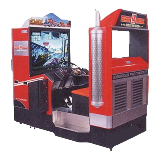
4. NAME OF PARTS MAIN BILLBOARD SUB BILLBOARD PILLAR L SHIFT LEVER STEERING HANDLE COIN CHUTE DOOR CASHBOX DOOR PTV BASE ACCELERATOR & BRAKE MAIN CABINET PILLAR R FIG. 4 a OVERVIEW AC UNIT FIG. 4 b SIDE VIEW TABLE 4 Width Length Height... -
Page 12: Accessories
5. ACCESSORIES When transporting the machine, make sure that the following parts are supplied. TABLE 5 ACCESSORIES KEY MASTER DESCRIPTION OWNERS MANUAL 220-5576 (2) Part No. (Qty.) 420-6545-01 (1) For opening/closing For the CASHBOX DOOR Note the doors Figures If Part No. has no description, the Number has not been registered or can not be registered. - Page 13 TOSHIBA MITSUBISHI FUSE 6.3A 125V Remote Controller used for Remote Controller used for 514-5086-6300 (1) adjustment of the projector. adjustment of the projector. Spare, see Section 17. See Section 14. See Section 14. 200-5536(1) 200-5532(1) TEST MODE WRITING POWER R / B R / G / B PIC-ADJ POSITION...
- Page 14 HOW TO USE THE CARTON BOX When requesting for the replacement/repair of this product's Game Board STOP (NAOMI BOARD), follow the instructions below. Transporting the Game Board in an undesignated status is unacceptable. An erroneous handling can cause parts IMPORTANT damage.
-
Page 15: Assembling And Installation
6. ASSEMBLING AND INSTALLATION Perform assembly work by following the procedure herein stated. Failing to comply with the instructions can cause electric shock hazard. Perform assembling as per this manual. Since this is a complex machine, erroneous assembling can cause an electric shock, machine damage and or not functioning as per specified performance. - Page 16 When carrying out the assembly work, follow the procedure in the following 7-item sequence: ASSEMBLING THE PTV INSTALLING THE MAIN BILLBOARD, PILLAR L, AND PILLAR R INSTALLING THE PTV SECURING IN PLACE (ADJUSTER ADJUSTMENT) POWER SUPPLY, AND EARTH CONNECTION TURNING POWER ON ASSEMBLY CHECK When assembling, make sure that tools such as a Phillips type screwdriver, wrench (for M16 hexagon bolt), socket wrench (M6, M8 hexagon bolt), ratchet handle, and the master key are...
- Page 17 ASSEMBLING THE PTV Secure the 2 Mask Holders to the PTV ceiling with the 2 Flat Head screws for FLAT HEAD SCREW (2 each) each. M4 X 12 Secure the Mask to the PTV with a total of 6 screws. MASK HOLDER TRUSS SCREW (2) M5 X 25,chrome,...
- Page 18 INSTALLING THE MAIN BILLBOARD, PILLAR L, AND PILLAR R Take out the 7 truss screws to remove the BACK PANEL COVER from the back of main cabinet. Take out the 2 hexagon bolts to remove the BACK PANEL from the back of main cabinet. Take out the 2 truss screws, unlock the lock, and remove the BACK LID.
- Page 19 Install the PILLAR L and PILLAR R to the left & right sides of main cabinet and secure with the 6 hexagon bolts for each. Fasten the 2 bolts from inside the BACK LID. The PILLAR R has wiring. Check with the connector portion. Install the PILLAR L to the left side and the PILLAR R to the right-hand side of main cabinet when facing from the PTV screen.
- Page 20 To secure the PILLAR, install the L-shaped Bracket from the seat side. Secure the PILLAR CABI BRACKET UPPER with the 3 truss screws and the PILLAR CABI BRACKET LOWER with the 4 truss screws. Perform this on the both sides. PILLAR CABI BRACKET UPPER TRUSS SCREW (3 each) M6 X 30,black...
- Page 21 Install the BACK PANEL, the BACK PANEL COVER, and the BACK LID to the main cabinet back. FIG. 6. 2 f Lift the MAIN BILLBOARD onto the 2 PILLARs by 2 persons. Use care so as not to pinch hands or damage wire. FIG.
- Page 22 By using a total of 4 truss screws from TRUSS SCREW (4 in total) inside the 2 PILLARs, secure the M5 X 50,black, flat washer used. MAIN BILLBOARD. FIG. 6. 2 h When performing work, be sure to use a step. www.seuservice.com...
- Page 23 Secure the END CAP BRACKET to the PILLAR with the 2 screws. Perform this on the both sides. Connect the wire connector of the MAIN BILLBOARD to the connector of the PILLAR R. SCREW (2 each) Connect the Connector. M4 X 20,black,w/flat & spring washers END CAP BRACKET PHOTO 6.
- Page 24 PIPE BRACKET By using the 2 screws, install the PIPE BRACKET to the END CAP BRACKET. SCREW (2 each) M4 X 20,w/flat & spring washers Install the PIPE SAFETY on to the PIPE PIPE SAFETY BRACKET with the 2 truss screws. Perform this on the both sides.
- Page 25 INSTALLING THE PTV Fit the PTV BASE and the main cabinet. The surface of PTV BASE fitting to the main cabinet is predetermined. Secure the PTV BASE and the main cabinet with a total of 6 hexagon bolts. FIG. 6. 3 a HEXAGON BOLT (4) PTV BASE M8 X 30,w/spring washer,...
- Page 26 Fasten the 2 screws tightly. Connect the 2 wire connectors from the main cabinet to the PTV Connector Panel. The signal connector has the MITSUBISHI securing screws at the both ends. Fasten the 2 screws PROJECTOR tightly after having connected the connector. At this time, use 3 persons to support the PTV.
- Page 27 Install the SUB BILLBOARD to the PTV ceiling. Insert the SUB BILLBOARD to the 2 Mask Holders on the PTV ceiling and secure with the 2 truss screws. To perform work safely and securely, be sure to use a step. Do not step on the PTV or the main cabinet to perform work. TRUSS SCREW (2) M5 X 16,chrome, flat washer used.
- Page 28 SECURING IN PLACE (ADJUSTER ADJUSTMENT) Make sure that all of the adjusters are in contact with the floor. If they are not, the cabinet can move and cause an accident. This product has 8 casters (4 for PTV BASE, 4 for MAIN CABINET) and 8 Adjusters (4 for PTV BASE, 4 for MAIN CABINET).
- Page 29 POWER SUPPLY, AND EARTH CONNECTION Be sure to independently use the power supply socket outlet equipped with an Earth Leakage Breaker. Using a power supply without an Earth Leakage Breaker can cause a fire when electric leakage occurs. Ensure that the "accurately grounded indoor earth terminal" and the earth wire cable are available (except in the case where a power cord plug with earth is used).
- Page 30 Connect one end of the earth wire to the AC Unit Connect the Earth Wire earth terminal, and the other end to the indoor earth to the Earth Terminal. terminal. The AC Unit earth terminal has a Bolt and Nut combination. Take off the Nut, pass the end of earth wire through the Bolt, and fasten the Nut.
- Page 31 TURNING POWER ON Turn the AC Unit's main switch on to supply power. When power is turned on, the fluorescent lamp inside the MAIN BILLBOARD lights up. The monitor displays NAOMI SYSTEM boot up and then proceeds to the advertise mode. During this time, the initialization setting is automatically performed.
- Page 32 ASSEMBLING CHECK In the TEST MODE, ascertain that the assembly has been made correctly and IC BD. is satisfactory (refer to Section 9). In the test mode, perform the following test: (1) MEMORY TEST Selecting the desired RAM TEST item on the test mode menu screen causes the on-board MEMORY TEST MODE memory to be tested automatically.
- Page 33 (3) INPUT TEST Selecting the INPUT TEST on the test mode INPUT TEST menu screen causes the screen (on which COIN CHUTE #1 each switch is tested) to be displayed. Press COIN CHUTE #2 each switch. For the coin switch test, insert SERVICE TEST a coin from the coin inlet with the coin chute...
-
Page 34: Precautions To Be Heeded When Moving The Machine
7. PRECAUTIONS TO BE HEEDED WHEN MOVING THE MACHINE When moving the machine, be sure to unplug the power plug. Moving the machine with the plug as is inserted can damage the power cord and cause fire and electric shock hazards. When moving the machine on the floor, retract the Adjusters and ensure that Casters make contact with the floor. - Page 35 GRIP Have casters make contact with the floor. FIG. 7 a When transporting the product in places with steps or step-like differences in grade, disassemble into each unit before transporting. 1 2 3 4 5 6 7 8 9 0 1 2 3 4 5 6 7 8 9 0 1 2 3 4 5 6 7 8 9 0 1 2 1 2 3 4 5 6 7 8 9 0 1 2 3 4 5 6 7 8 9 0 1 2 3 4 5 6 7 8 9 0 1 2 1 2 3 4 5 6 7 8 9 0 1 2 3 4 5 6 7 8 9 0 1 2 3 4 5 6 7 8 1 2 3 4 5 6 7 8 9 0 1 2 3 4 5 6 7 8 9 0 1 2 3 4 5 6 7 8 9 0 1 2 1 2 3 4 5 6 7 8 9 0 1 2 3 4 5 6 7 8 9 0 1 2 3 4 5 6 7 8 9 0 1 2 1 2 3 4 5 6 7 8 9 0 1 2 3 4 5 6 7 8 9 0 1 2 3 4 5 6 7 8 1 2 3 4 5 6 7 8 9 0 1 2 3 4 5 6 7 8 9 0 1 2 3 4 5 6 7 8 9 0 1 2 1 2 3 4 5 6 7 8 9 0 1 2 3 4 5 6 7 8 9 0 1 2 3 4 5 6 7 8 9 0 1 2 1 2 3 4 5 6 7 8 9 0 1 2 3 4 5 6 7 8 9 0 1 2 3 4 5 6 7 8 1 2 3 4 5 6 7 8 9 0 1 2 3 4 5 6 7 8 9 0 1 2 3 4 5 6 7 8 9 0 1 2 1 2 3 4 5 6 7 8 9 0 1 2 3 4 5 6 7 8 9 0 1 2 3 4 5 6 7 8 9 0 1 2 1 2 3 4 5 6 7 8 9 0 1 2 3 4 5 6 7 8 9 0 1 2 3 4 5 6 7 8...
-
Page 36: Contents Of Game
8. CONTENTS OF GAME The following explanations apply to the case the product is functioning satisfactorily. Should there be any moves different from the following contents, some sort of faults may have occurred. Immediately look into the cause of the fault and eliminate the cause thereof to ensure satisfactory operation. - Page 37 OUTLINE OF THE GAME • This is a single, driving game in which the player competes with rivals by driving a Trailer Truck to cross America. • When coins are inserted to gain credits, the START button starts flashing. Press the START button to proceed to the SELECTOR mode where you can select your truck and trailer.
- Page 38 HORN AT THE ASSISTANT DRIVER'S SEAT STEERING WHEEL OPERATION VIEW CHANGE BUTTON START BUTTON GEAR BRAKE ACCEL. CONTROL PANEL and ACCEL. & BRAKE HORN AT THE DRIVER'S SEAT <STEERING WHEEL> SELECTOR : Turn right or left to select an object. GAME PLAY : Operate the Trailer Truck.
- Page 39 SELECTOR TRUCK SELECT Select the truck from among ASPHALT COWBOY, STREAMLINE, HIGHWAY CAT, LONG HORN, and NIHONMARU (not available for Korea version). Each truck's abilities in SPEED, TORQUE, and TOUGHNESS differ. TRAILER SELECT When starting in the stages 2, 3, and 4, select the trailer for towing from the 2 trailers. The weight, the length, and the transportation fee differ.
- Page 40 NAME ENTRY If your score falls within the top 5, you can enter your name. VIEWING THE GAME SCREEN REARVIEW MIRROR DESTINATION TIME LIMIT TRANSPORTAION GEAR CHANGE INDICATOR GEAR CONDITION TACHOMETER www.seuservice.com...
- Page 41 <DESTINATION> Name of the destination point. <TIME LIMIT> Indicates the player's playable time. Additional time will be added when passing the CHECKPOINT and obtaining TIME BONUS. <REARVIEW MIRROR> Indicates the rear condition while DRIVER'S VEIW is being selected. <TRANSPORTATION FEE> Indicates the fee you receive when you reach the destination.
-
Page 42: Explanation Of Test And Data Display
9. EXPLANATION OF TEST AND DATA DISPLAY By operating the switch unit, periodically perform the tests and data check. When installing the machine initially or collecting cash, or when the machine does not function correctly, perform checking in accordance with the explanations given in this section. The following shows tests and modes that should be utilized as applicable. -
Page 43: Switch Unit And Coin Meter
9 - 1 SWITCH UNIT AND COIN METER Never touch places other than those specified. Touching places not specified can cause electric shock and short circuit accidents. Adjust to the optimum sound volume by considering the environmental STOP requirements of the installation location. If the COIN METER and the game board are electrically disconnected, game IMPORTANT play is not possible. -
Page 44: System Test Mode
9 - 2 SYSTEM TEST MODE STOP The contents of settings changed in the TEST mode are stored when the test mode is finished from EXIT in the menu mode. If the power is turned off before the TEST mode is finished, the contents of setting change become IMPORTANT! ineffective. -
Page 45: Game Test Mode
9- 3 GAME TEST MODE A. GAME TEST MODE MENU (MAIN MENU) 18WHEELER TEST MENU SYSTEM MENU JAPAN VERSION INPUT TEST RAM TEST OUTPUT TEST JVS TEST SOUND TEST SOUND TEST GAME ASSIGNMENTS C.R.T. TEST VOLUME SETTING SYSTEM ASSIGNMENTS BOOKKEEPING COIN ASSIGNMENTS BACKUP DATA CLEAR BOOKKEEPING... - Page 46 B. INPUT TEST When the INPUT TEST is selected, the following screen is displayed on the monitor. INPUT TEST COIN CHUTE #1 COIN CHUTE #2 SERVICE TEST START VIEW HORN SHIFT [L] SHIFT [H] SHIFT [R] HANDLE ACCEL BRAKE PRESS TEST + SERVICE BUTTON TO EXIT •...
- Page 47 C. OUTPUT TEST Selecting the OUTPUT TEST displays the following screen on the monitor. The condition of each lamp and motor can be checked. OUTPUT TEST START LAMP VIEW LAMP HORN LAMP ROLL LEFT ROLL RIGHT ->EXIT SELECT WITH SERVICE BUTTON AND PRESS TEST BUTTON •...
- Page 48 D. SOUND TEST Selecting the SOUND TEST displays the following screen on the monitor. In this mode, sounds used in the game can be checked. SOUND TEST B.G.M 0/ X X EFFECT 0/ X X [_______] 0/ X X [_______] ->...
- Page 49 E. GAME ASSIGNMENTS Selecting the GAME ASSIGNMENTS displays the following screen on the monitor. Setting for the game can be performed. The contents of setting changes will be effective when the TEST MODE is finished properly. If the setting changes are made, be sure to exit from the TEST MODE. GAME ASSIGNMENTS START TIME [VERY EASY]...
- Page 50 F. VOLUME SETTING Selecting the VOLUME SETTING displays the following screen on the monitor. The volume detecting the steering wheel operation can manually be set. The value can be stored when exiting from the item. VOLUME SETTING HANDLE SETTING SET CENTER [LOCK] 00H ->...
- Page 51 G. BOOKKEEPING Selecting the BOOKKEEPING displays the data of operating status in 2 pages. Press the TEST button to proceed to the next screen. When the TEST button is pressed in the 2/2 PAGE, the screen returns to the MENU mode. BOOKKEEPING 1/2 NUMBER OF GAMES NUMBER OF CONTINUE...
- Page 52 H. BACKUP DATA CLEAR Selecting the BACKUP DATA CLEAR displays the following screen on the monitor. The contents of BOOKKEEPING in the GAME TEST MODE and the ranking data can be cleared. Note that this operation does not affect the contents of GAME ASSIGNMENTS and the VOLUME SETTING.
-
Page 53: Control Panel(Handle Mecha)
10. CONTROL PANEL (HANDLE MECHA) Before starting to work, ensure that the Power SW is OFF. Failure to observe this can cause electric shock or short circuit. Use care so as not to damage wirings. Damaged wiring can cause electric shock or short circuit. - Page 54 Take out the 4 truss screws at the center of the steering wheel to remove the FRAME HORN BUTTON and the CAP HORN BUTTON. A small part (PIN HORN BUTTON) is attached to the CAP HORN BUTTON. Be sure to keep it. Pull out the ROD HORN BUTTON.
- Page 55 Take out the 4 screws, disconnect a connector, and remove the HORN BUTTON at the assistant driver's seat. (See sec. 15) Take out the 11 screws to remove the CONTROL PANEL COVER. Wiring connection is inside the CONTROL PANEL COVER. Use care so as not to damage wiring. The CONTROL PANEL COVER is made of plastic.
- Page 56 Take out the 4 screws to remove the LID TOP FRONT. Disconnect the 2 wire connectors of the motor inside the LID TOP FRONT. TRUSS SCREW (4) M4 X 30,black LID TOP FRONT Disconnect the connector. PHOTO 10. 1 c www.seuservice.com...
- Page 57 Take out a total of 6 screws and the 2 hexagon bolts which secure the HANDLE MECHA. HOXAGON BOLT (2) M6 X 25,w/spring washer, flat washer used. SCREW (6 in total) M5 X 16,w/flat & spring washers PHOTO 10. 1 d www.seuservice.com...
- Page 58 Remove the HANDLE MECHA. Use care when performing work. PHOTO 10. 1 e When putting the HANDLE MECHA, be sure to have the gear and the sensor portions face upper. Failure to observe this may damage the parts due to its own weight. FIG.
-
Page 59: Volume Adjustment/Replacement
10 - 2 VOLUME ADJUSTMENT/REPLACEMENT Volume adjustment/replacement should be performed after the HANDLE MECHA has been removed as per 10-1. ADJUSTMENT In order to turn the HANDLE SHAFT, insert the STEERING HANDLE to the HANDLE SHAFT. Secure the HANDLE at the centering position. Loosen the 2 screws which secure the VOLUME BRACKET to push the gear out of mesh. - Page 60 REPLACEMENT Disconnect the volume's wire connector. Take out the 2 screws which secure the VOLUME BRACKET to remove the BRACKET together with the volume. Take out the 2 screws, remove the VOLUME GEAR, and replace the VOLUME. With the HANDLE SHAFT being at the centering position, bring the gear into mesh so that the status of the volume's shaft is as shown in the Fig.
-
Page 61: Shift Lever
11. SHIFT LEVER Before starting to work, ensure that the Power SW is OFF. Failure to observe this can cause electric shock or short circuit. Use care so as not to damage wirings. Damaged wiring can cause electric shock or short circuit. If the Shift Lever operation is not satisfactory, remove the Shift Lever in the following procedure and replace the microswitch. -
Page 62: Switch Replacement
11 - 2 SWITCH REPLACEMENT Each Microswitch is secured with 2 screws. Remove the 2 screws and replace the Microswitch. MICROSWITCH 509-5636 PHOTO 11. 2 SCREW (2)M2.3 X 12, w/flat & spring washers FIG. 11. 2 After replacing the Switch, check to see if the switch is inputted as per Shift Lever operation in the Test Mode. -
Page 63: Accelerator & Brake
12. ACCELERATOR & BRAKE Before starting to work, ensure that the Power SW is OFF. Failure to observe this can cause electric shock or short circuit. Use care so as not to damage wirings. Damaged wiring can cause electric shock or short circuit. Do not touch undesignated places. -
Page 64: Adjusting Or Replacing The Volume
12 - 2 ADJUSTING OR REPLACING THE VOLUME The appropriate value for both ACCEL. Volume and Brake Volume is under 30H when released and over C0H when stepped on. Check Volume values in the TEST mode. Since work is performed inside the energized cabinet, be very careful so as not to touch undesignated places. Touching places not specified can cause electric shock or short circuit. -
Page 65: Greasing
REPLACEMENT TRUSS SCREW(2) M4 X 8 Turn the power off. Take out the 2 screws and remove POTENTIOCOVER the Potentiocover (FIG. 12. 2 c). Disconnect the connector of the volume to be replaced. Remove the screw which secures the Potentiobase (FIG. 12. 2 b). Remove the Potentiobase together with the volume as is attached. -
Page 66: Coin Selector
13. COIN SELECTOR HANDLING THE COIN JAM If the coin is not rejected when the REJECT button is pressed, open the coin chute door and open the selector gate. After removing the jammed coin, put a normal coin in and check to see that the selector correctly functions. - Page 67 OPTIONAL DOLLAR BILL ACCEPTOR THE COIN DOOR ASSEMBLY USED ON 18 Wheeler Deluxe COMES EQUIPPED TO ACCEPT A DOLLAR BILL ACCEPTOR. ALL NEEDED WIRING CONNECTIONS ARE CONVIENENTLY LOCATED INSIDE THE GAME FOR THIS APPLICATION. THE COIN DOOR CAN ACCCOMMODATE THE FOLLOWING VALIDATOR(S): FORWARD-MOST Mars 2000 series...
- Page 68 www.seuservice.com...
- Page 69 www.seuservice.com...
-
Page 70: Projector
14. PROJECTOR Since the Projector has been adjusted at the time of shipment, avoid making further adjustments without good reason. The Projector is subject to color deviation due to Convergence deviation caused STOP by the geomagnetism at the installation location and peripheral magnetic field. After the installation of machine, and before commencing operation, check for IMPORTANT Convergence deviation and if deviated, make adjustments. -
Page 71: Adjustment Of Toshiba Projector
14 - 2 ADJUSTMENT OF TOSHIBA PROJECTOR SETTING THE INTERFACE In this product, set to INPUT LEVEL: 0.7V and IMPEDANCE: 75É∂. Failure STOP to observe this can cause CRT membrane to burn or Shutdown device to function resulting in power off. IMPORTANT The Projector's Connector Panel contains the Interface setting SW. - Page 72 AUTOMATIC COLOR MATCHING The Projector may be subject to color deviations affected by earth magnetism, the building steel frames, etc. When the Projector is initially installed or the Projector's installation position is changed, have the color matching performed automatically. Keep pressing the P button (red) for approximately 3 seconds to have the ensuing movements performed automatically.
- Page 73 ADJUSTING THE ON-SCREEN CONTRAST Although the on-screen picture quality has been adjusted at the time of shipment from the factory, the on-screen contrast can be readjusted if desired. When the Game Board is replaced, readjustment may be necessary. Changing the CONTRAST causes the light and shade of the on-screen images to be changed.
- Page 74 ADJUSTING THE SCREEN BRIGHTNESS Although the on-screen picture quality has been adjusted at the time of shipment from the factory, readjustment can be made if desired. When the Game Board is replaced, readjustment may be necessary. Changing the BRIGHTNESS causes the brightness of the on-screen images of black portions to be changed.
- Page 75 ADJUSTING THE ON-SCREEN DISPLAY POSITION Although the on-screen display position (H. POSI, V. POSI) has been adjusted at the time of shipment from the factory, readjustment can be made if desired. When the Game Board is replaced, readjustments may be necessary. Press either PIC - ADJ button.
- Page 76 ADJUSTING THE SCREEN SIZE Although the on-screen size (H. SIZE, V. SIZE) has been adjusted at the time of shipment from the factory, readjustment can be made if desired. When the Game Board is replaced, readjustments may be necessary. Press either PIC - ADJ button.
- Page 77 CONVERGENCE ADJUSTMENT (manual color matching) To avoid circuitry malfunctioning due to electrical load increase, never utilize CONVERGENCE ADJUSTMENT (Line Convergence Adjustment in particular) for adjusting screen size changes. There is no means to restore the Convergence Adjustment data once stored, to its original state.
- Page 78 STATIC CONVERGENCE ADJUSTMENT In the static convergence adjustment, each of red and blue images is comprehensively moved to and superimposed on the green color. If automatic color matching function is not sufficiently satisfactory, perform this adjustment. Be sure to perform automatic color matching before starting the above adjustment.
- Page 79 POINT CONVERGENCE ADJUSTMENT In the POINT CONVERGENCE adjustment, each of red, green and blue images is partially moved for color matching. The adjustment may be necessary when the Game Board is replaced or changed, or screen size is changed. Be sure to perform automatic color matching before starting the adjustment.
- Page 80 LINE CONVERGENCE ADJUSTMENT In the LINE CONVERGENCE ADJUSTMENT, the adjustment point of the column line (verti- cal) or row line (horizontal) is comprehensively moved for color matching. It is convenient to utilize this adjustment when the color of the column line or row line is uniformly deviated. Keep pressing the TEST button for approximately 3 seconds.
-
Page 81: Adjustment Of Mitsubishi Projector
14 - 3 ADJUSTMENT OF MITSUBISHI PROJECTOR For the operation of Remote Control, use only the Keys of R/B, STOP (UP shift), (LEFT shift), (DOWN shift), (RIGHT shift), TEST, - , + , and PICTURE. Do not press keys other than those explained in this IMPORTANT manual. - Page 82 • POWER KEY......This does not have power ON/OFF function. Does not function even if it is pressed. • R/B KEY ........ Used to select "R" for red adjustment or "B" for blue adjustment in the STATIC CONVERGENCE ADJUSTMENT mode. •s(UP shift) KEY ....
- Page 83 STATIC CONVERGENCE ADJUSTMENT RED 31K Press the TEST KEY to change the screen to Red Line H:+75 V:-11 Adjustment mode. Superimpose the red line on the green line. When the red line is superimposed on the green line, the green line turns to yellow or white. To MOVE RED LINE: key to move it left.
-
Page 84: Replacing The Fluorescent Lamp,And Lamps
15. REPLACING THE FLUORESCENT LAMP, AND LAMPS When performing work, be sure to turn power off. Working with power on can cause electric shock and short circuit hazards. The Fluorescent Lamp, when it gets hot, can cause burn. Be very careful when replacing the Fluorescent Lamp. - Page 85 Remove the MAIN BILLBOARD PLATE. PHOTO 15 c MAIN BILLBOARD PLATE Replace the fluorescent lamp inside the BILLBOARD. PHOTO 15 d FLUORESCENT LAMP 32W: 390-5251-32-01 GLOW BULB: 390-5638-5P THE BUTTON FOR THE HORN IN THE ASSISTANT DRIVER'S SEAT A wiring connection is inside the horn button. When removing, use care so as not to damage wiring.
- Page 86 A wire connector is connected to the horn button. Disconnect the connector, and the horn button can be removed. Firmly pinch the switch portion at the bottom of the button and pull it out of the button portion. Pull out the lamp vertically and replace. Disconnect the connector.
- Page 87 A connector is connected to the start button and the view change button. Disconnect the connector, and the ASSY VR BUTTON START & VIEW 1 can be removed. Disconnect the connector. PHOTO 15 i The lamp is on the PCB side. Turn the metallic parts of the 2 buttons, unlock and remove the PCB from the buttons.
-
Page 88: Periodic Inspection Table
16. PERIODIC INSPECTION TABLE The items listed below require periodic check and maintenance to retain the performance of this machine and to ensure safe business operation. Be sure to check once a year to see if Power Cords are damaged, the plug is securely inserted, dust is accumulated between the Socket Outlet and the Power Plug, etc. -
Page 89: Troubleshooting
17. TROUBLESHOOTING In order to prevent electric shock and short circuit, be sure to turn power off before performing work. Be careful so as not to damage wirings. Damaged wiring can cause electric shock or short circuit. After removing the cause of the functioning of the Circuit Protector, reinstate the Circuit Protector. - Page 90 TABLE 17 b PROBLEMS CAUSE COUNTERMEASURES No sound is Sound volume adjustment is not Adjust sound volume (see Sec. 9). emitted. appropriate. Board and Amplifier malfunctioning. Perform the sound test and confirm (see Sec. 9). Operation of The fuse on the AMP BASE is blown. Replace fuse.
- Page 91 REPLACMENT OF FUSE Fuse replacements other than those specified can cause accidents and are strictly forbidden. In case fuse replacements other than those stated in this manual are necessary, contact where you purchased the product from for inquiries regarding this matter. In order to prevent an electric shock, be sure to turn power off and unplug from the socket outlet before performing work by touching the internal parts of the product.
-
Page 92: Game Board
18. GAME BOARD In order to prevent electric shock and short circuit hazards, be sure to turn power off before performing work. Be careful so as not to damage wirings. Damaged wiring can cause fire, electric shock or short circuit. Do not expose the Game BD, etc. - Page 93 Disconnect the 4 connectors connected to the IC BOARD next to the NAOMI GAME BOARD. It is not necessary to disconnect the leftmost 2 connectors out of the 3 connectors on the IC BD. Pull out the 8P connector at the AMP BD side.
-
Page 94: Composition Of Game Board
18 - 2 COMPOSITION OF GAME BOARD Ensure that the DIP SW setting is performed as designated. Failure to observe STOP this may cause functioning not suitable for the actual operation, or malfunctioning. IMPORTANT ASSY CASE NAO PTR USA(840-0023D-01):USA ASSY CASE NAO PTR EXP(840-0023D-02):OTHERS ASSY CASE NAO PTR KOR(840-0023D-03):KOREA ASSY CASE NAO PTR AUS(840-0023D-04):AUSTRALIA SCREW (4) -
Page 95: Error Display(Drive Control Board)
18 - 3 ERROR DISPLAY (DRIVE CONTROL BOARD) Be careful so as not to damage wirings. Damaged wiring can cause electric shock and short circuit hazards. Do not touch undesignated places. Touching places not specified can cause electric shock and short circuit hazards. Inside the LID TOP FRONT is the Drive Control Board. - Page 96 Among the ERROR display as per Table 18.3, each of Er 01, 02, 20 and 22 (Error Code e7, 6, 0 and 9) is displayed before the Advertise mode is displayed if an irregularity is found during initialization setting movements when power is turned on. From among error displays as per Table 18.3, Er 23, 24, 25, and 30 (Error Code e1, 2, 3 and a) indicate On-Board 7-SEG error display when an irregularity is found during game and ADVERTISE mode.
-
Page 97: Design Related Parts
19. DESIGN RELATED PARTS For the Warning Display stickers, refer to Section 1. www.seuservice.com... -
Page 98: Parts List
20. PARTS LIST www.seuservice.com... - Page 99 1 TOP ASSY PTR DX (D-1/2) www.seuservice.com...
- Page 100 1 TOP ASSY PTR DX (D-2/2) ITEM NO. PART NO. DESCRIPTION NOTE PTR-0500 ASSY PTV PTR-0550 ASSY PTV BASE PTR-1000 ASSY MAIN CABINET PTR-1600 ASSY SUB BILLBOARD 421-7308- ~ DENOMI SH 1GAME, ~ 440-CS0186-EG STICKER C EPILEPSY 40 ENG 440-WS0002XEG STICKER W POWER OFF ENG 421-7020 STICKER CAUTION FORK...
- Page 101 2 ASSY PTV (PTR-0500) ITEM NO. PART NO. DESCRIPTION NOTE PTR-0510 PTV W/STICKER PTR MGL-1150 ASSY MASK HOD-1101 PTV HOLDER RAL-0501 MASK HOLDER 000-F00412 M SCR FH M4 X 12 000-P00516-W M SCR PH W/FS M5 X 16 000-P00520-W M SCR PH W/FS M5 X 20 000-T00525-0C M SCR TH CRM M5 X 25 068-552016-0C...
- Page 102 3 PTV W/STICKER PTR (PTR-0510) ITEM NO. PART NO. DESCRIPTION NOTE PTR-0511 STICKER PTV SIDE L PTR-0512 STICKER PTV SIDE R 200-5788-31 PROJECTION DSPL T 50TYPE 31K 200-5799-31 PROJECTION DSPL M 50TYPE 31K www.seuservice.com...
- Page 103 4 ASSY PTV BASE (PTR-0550) ITEM NO. PART NO. DESCRIPTION NOTE PTR-0551 PTV BASE SCR-1008 NUT PLATE FOR CASTER ARC-1006 LEG BRACKET 117-5233 PLATE LEG BRACKET BLACK 601-9377 CASTER FAI=75 601-5699X LEG ADJUSTER BOLT M16 X 75 050-H01600-0B HEX NUT BLK M16 030-000630-SB HEX BLT BLK W/S M6 X 30 011-P03512...
- Page 104 5 ASSY SUB BILLBOARD (PTR-1600) ITEM NO. PART NO. DESCRIPTION NOTE PTR-1601 SUB BILLBOARD BASE PTR-1602 SUB BILLBOARD PLATE PTR-1604 SIDE PLATE L PTR-1605 SIDE PLATE R 000-T00412-0C M SCR TH CRM M4 X 12 www.seuservice.com...
- Page 105 6 ASSY MAIN CABINET (PTR-1000) (D-1/4) www.seuservice.com...
- Page 106 6 ASSY MAIN CABINET (PTR-1000) (D-2/4) www.seuservice.com...
- Page 107 6 ASSY MAIN CABINET (PTR-1000) (D-3/4) ITEM NO. PART NO. DESCRIPTION NOTE PTR-1070 ASSY PILLAR L PTR-1075 ASSY PILLAR R PTR-1080 ASSY BACK PANEL PTR-1100 ASSY SUB-CABI PTR-1200 ASSY COINCHUTE TOWER PTR-1500 ASSY MAIN BILLBOARD PTR-2100 ASSY HIGH/LOW/BACK SHIFTER PTR-2500 ASSY HANDLE MECHA PTR-4000 ASSY MAIN BD...
- Page 108 6 ASSY MAIN CABINET (PTR-1000) (D-4/4) ITEM NO. PART NO. DESCRIPTION NOTE 130-5096 ASSY SERVO SPEAKER BOX 130-5196 WOOFER 4OHM 80W 130-5172 BASS SHAKER 509-5966 SW PB OBSA-60UM 14V 3.8W PTR 280-5275-SR10 CORD CLAMP SR10 280-0419 HARNESS LUG 270-5117 FERRITE CORE TDK ZCAT3035-1330 601-0460 PLASTIC TIE BELT 100 MM 000-T00412-0C...
- Page 109 ASSY STEERING UNIT www.seuservice.com...
- Page 110 ASSY HANDLE MECHA www.seuservice.com...
- Page 111 7 ASSY SUB-CABI (PTR-1100) (D-1/3) www.seuservice.com...
- Page 112 7 ASSY SUB-CABI (PTR-1100) (D-2/3) ITEM NO. PART NO. DESCRIPTION NOTE PTR-1190 ASSY BACK LID PTR-1012 BRKT HORN BUTTON STR-1070 FAN UNIT PTR-1101 MAIN CABINET PTR-1102 SEAT BRKT PTR-1103 SEAT BRKT UPPER PTR-1104 BACK PLATE PTR-1107 DUMMY SHAFT PTR-1108 CTRL COVER BRKT A PTR-1109 CTRL COVER BRKT B PTR-1111...
- Page 113 7 ASSY SUB-CABI (PTR-1100) (D-3/3) ITEM NO. PART NO. DESCRIPTION NOTE PTR-60005 WIRE HARN AC FRONT PTR-60006 WIRE HARN AC BACK PTR-60031 WIRE HARN MOTOR PTR-60032 WIRE HARN ENCODER PTR-60103 WIRE HARN EARTH SHIFTER 600-6972-1200 WIRE HARN EARTH ID5 1200MM 600-6972-1800 WIRE HARN EARTH ID5 1800MM 600-6972-0750...
- Page 114 8 ASSY BACK LID (PTR-1190) ITEM NO. PART NO. DESCRIPTION NOTE PTR-1191 BACK LID DP-1148X LKG TNG 117-0062 PLATE LOCK RETAINER 253-5460-01 AIR VENT BLACK 220-5575 CAM LOCK MASTER W/O KEY 000-T00416-0B M SCR TH BLK M4 X 16 www.seuservice.com...
- Page 115 9 ASSY WIRE (PTR-6001) ASSY WIRE (PTR-6001) is comprised of the following wire harnesses. An ASSY DRG. is unavailable. ITEM NO. PART NO. DESCRIPTION NOTE 601-0460 PLASTIC TIE BELT 100 MM PTR-60018 WIRE HARN WOOFER 2 PTR-60019 WIRE HARN SPEARKER 2 PTR-60020 WIRE HARN VOLUME 2 PTR-60024...
- Page 116 10 FAN UNIT (STR-1070) Connector ITEM NO. PART NO. DESCRIPTION NOTE 105-5340-01 FAN BRKT LONG 260-0011-02 AXIAL FLOW FAN AC100V 50-60HZ 601-8543 FAN GUARD 000-P00312-W M SCR PH W/FS M3 X 12 www.seuservice.com...
- Page 117 11 FAN UNIT OPPOSITE FLOW (STR-1070-01) Connector ITEM NO. PART NO. DESCRIPTION NOTE 105-5340-01 FAN BRKT LONG 260-0011-02 AXIAL FLOW FAN AC100V 50-60HZ 601-8543 FAN GUARD 000-P00312-W M SCR PH W/FS M3 X 12 www.seuservice.com...
- Page 118 12 AC UNIT (PTR-1060) (D-1/2) www.seuservice.com...
- Page 119 12 AC UNIT (PTR-1060) (D-2/2) ITEM NO. PART NO. DESCRIPTION NOTE FRI-1021 AC BRACKET 421-7468-01 STICKER C.P W/PIC 421-8202 STICKER EARTH MARK FRI-1022 CONNECTOR LID 214-0202 AC INLET PANEL TYPE 280-0417 TERMINAL BINDING POST BLACK TAIWAN NOT USED OTHERS 509-5453-91-V-B SW ROCKER J8 V-B 512-5046-10000 C.P 10000MA CE UL...
- Page 120 13 ASSY PILLAR L (PTR-1070) (D-1/2) www.seuservice.com...
- Page 121 13 ASSY PILLAR L (PTR-1070) (D-2/2) ITEM NO. PART NO. DESCRIPTION NOTE PTR-1071 PILLAR BASE PTR-1072 PILLAR COVER BRKT PTR-1073 UPPER BRKT PTR-1074 LOWER BRKT PTR-1003 PILLAR COVER PTR-1004 END CAP PTR-1017 END CAP BRKT LOWER 011-P03512 TAP SCR PH 3.5 X 12 000-P00420-WB M SCR PH W/FS BLK M4 X 20 000-T00412-0C...
- Page 122 14 ASSY PILLAR R (PTR-1075) (D-1/2) www.seuservice.com...
- Page 123 14 ASSY PILLAR R (PTR-1075) (D-2/2) ITEM NO. PART NO. DESCRIPTION NOTE PTR-1071 PILLAR BASE PTR-1072 PILLAR COVER BRKT PTR-1073 UPPER BRKT PTR-1074 LOWER BRKT PTR-1003 PILLAR COVER PTR-1004 END CAP PTR-1017 END CAP BRKT LOWER 280-0419 HARNESS LUG 011-P03512 TAP SCR PH 3.5 X 12 000-P00420-WB M SCR PH W/FS BLK M4 X 20...
- Page 124 15 ASSY BACK PANEL (PTR-1080) ITEM NO. PART NO. DESCRIPTION NOTE PTR-1081 BACK PANEL PTR-1082 DESIGN PLATE PTR-1083 DESIGN PILLAR PTR-1084 DESIGN SIDE PILLAR PTR-1085 STICKER GRILLE PATTERN 000-T00416-0C M SCR TH CRM M4 X 16 www.seuservice.com...
- Page 125 16 ASSY COINCHUTE TOWER (PTR-1200) (D-1/2) www.seuservice.com...
- Page 126 16 ASSY COINCHUTE TOWER (PTR-1200) (D-2/2) ITEM NO. PART NO. DESCRIPTION NOTE INY-1180 SW UNIT PTR-1201 TOWER COVER L APC-0301 COINCHUTE TOWER APC-0302 METER HOLE LID DRT-0301X COIN METER BRKT DP-1167 TNG LKG 105-5171 CHUTE PLATE SINGLE 253-5366 CASH BOX 421-7501-02 STICKER 6.3V 0.15A 440-WS0002XEG...
- Page 127 17 SW UNIT (INY-1180) ITEM NO. PART NO. DESCRIPTION NOTE INY-1181 SW BRKT 421-8911 STICKER SW UNIT 220-5179 VOL CONT B-5K OHM 509-5028 SW PB 1M 601-0042 KNOB 22 MM 310-5029-D20 SUMITUBE F D 20 MM 601-0460 PLASTIC TIE BELT 100 MM 600-6609-32 WIRE HARN TEST &...
- Page 128 18 ASSY MAIN BILLBOARD (PTR-1500) (D-1/2) www.seuservice.com...
- Page 129 18 ASSY MAIN BILLBOARD (PTR-1500) (D-2/2) ITEM NO. PART NO. DESCRIPTION NOTE PTR-1501 MAIN BILLBOARD BASE PTR-1502 MAIN BILLBOARD PLATE PTR-1503 MAIN BILLBOARD COVER PTR-1504 SASH PTR-1505 BILL JOINT BRKT PTR-1506 BILL WIRE COVER PTR-1507 SASH LOWER PTR-1508 SASH BRKT PTR-1509 SIDE GUIDE L PTR-1510...
- Page 130 19 ASSY HIGH/LOW/BACK SHIFTER (PTR-2100) (D-1/2) www.seuservice.com...
- Page 131 19 ASSY HIGH/LOW/BACK SHIFTER (PTR-2100) (D-2/2) ITEM NO. PART NO. DESCRIPTION NOTE SPG-2151 SHIFT KNOB SPG-2152 STOPPER RUBBER SPG-2153 FRONT BASE SPG-2154 SLIDE COVER SPG-2155 SLIDE PLATE SPG-2156 REAR BASE SPG-2157 RUBBER BLOCK 45 SPG-2158 RUBBER BLOCK 65 SPG-2159 INSULATOR SHEET SPG-2160X SHAFT CASE SPG-2161...
- Page 132 20 ASSY ACCEL&BRAKE (SPG-2200) (D-1/2) www.seuservice.com...
- Page 133 20 ASSY ACCEL&BRAKE (SPG-2200) (D-2/2) ITEM NO. PART NO. DESCRIPTION NOTE SPG-2201 BASE SPG-2202 ACCEL PEDAL SPG-2203 BRAKE PEDAL SPG-2204 ACCEL SPRING SPG-2205 BRAKE SPRING SPG-2206 SHAFT SPG-2207 ACCEL GEAR SPG-2208 BRAKE GEAR SPG-2209 NEUTRAL STOPPER SPG-2210 VR PLATE ACCEL SPG-2211 VR PLATE BRAKE SPG-2212...
- Page 134 21 ASSY HANDLE MECHA (PTR-2500) (D-1/2) www.seuservice.com...
- Page 135 21 ASSY HANDLE MECHA (PTR-2500) (D-2/2) ITEM NO. PART NO. DESCRIPTION NOTE PTR-2502 HANDLE SHAFT PTR-2503 STOPPER BLOCK PTR-2590 ASSY TOP PLATE HANDLE MECHA PTR-2505 STOPPER RING A PTR-2506 STOPPER RING B PTR-2515 MOTOR BASE PTR-2516 BEARING BASE PTR-2550 SENSOR UNIT PTR-2521 COVER BRKT PTR-2523...
- Page 136 25 SENSOR UNIT (PTR-2550) LIGHT RECEIVING SIDE LIGHT EMITTING SIDE ITEM NO. PART NO. DESCRIPTION NOTE PTR-2551 SENSOR BEKT PTR-2552 GUIDE RING 370-5226 PHOTO SENSOR OMT-01DAMP NEW 280-5275-SR10 CORD CLAMP SR10 000-P00312-W M SCR PH W/FS M3 X 12 www.seuservice.com...
- Page 137 27 ASSY VR BUTTON START AND 1VIEW (PTR-2600) ITEM NO. PART NO. DESCRIPTION NOTE APC-2151X VR BUTTON BRKT 171-6478B PC BD LIGHTING SWX5 PTR-2601 STICKER VR BUTTON 212-5205-12 CONN JST M 12P RTA 509-5560-Y PB SW W/L 6V 1L Y 509-5561-S PB SW W/L 6V 5L S www.seuservice.com...
- Page 138 24 ASSY MAIN BD (PTR-4000) NOTE: Make sure that there is no wiring, etc. in the slash mark portions. ITEM NO. PART NO. DESCRIPTION NOTE PTR-4001 MAIN BD BASE 840-0023D-02 ASSY CASE NAO PTR EXP OTHERS 840-0023D-04 ASSY CASE NAO PTR AUS AUSTRALIA 840-0023D-03 ASSY CASE NAO PTR KOR...
- Page 139 25 ASSY CONTROL BD (PTR-4100) NOTE: Make sure that there is no wiring, etc. in the slash mark portions. ITEM NO. PART NO. DESCRIPTION NOTE PTR-4101 CONTROL BD BASE 838-12912-01 SERVO MOTOR DRIVE BD NEW 838-13992 DRIVE BD PTR 280-0419 HARNESS LUG 011-P00325 TAP SCR PH 3 X 25...
- Page 140 26 ASSY AMP BD (PTR-4200) (D-1/2) www.seuservice.com...
- Page 141 26 ASSY AMP BD (PTR-4200) (D-2/2) ITEM NO. PART NO. DESCRIPTION NOTE PTR-4201 AMP BD BASE DRT-4502 FAN MOTOR BRKT 421-7914-250630 STICKER AC 250V 6.3A 601-10369 STEREO PWR AMP 47 560-5419-V XFMR 100V 23V9.6A X 2 838-13723 WOOFER AMP 50W X 2 260-0011-02 AXIAL FLOW FAN AC100V 50-60HZ 601-8543...
- Page 142 27 ASSY PWR SPLY (PTR-4300) NOTE: Make sure that there is no wiring, etc. in the slash mark portions. ITEM NO. PART NO. DESCRIPTION NOTE PTR-4301 PWR SPLY BASE PTR-4302 CONN BRKT VL3P PTR-4303 CONN BRKT UP18P 838-11856-UL CONNECT BD UL 280-5009-01 CORD CLAMP 21 280-0419...
- Page 143 28 ASSY TOP PLATE HANDLE MECHA (PTR-2590) ITEM NO. PART NO. DESCRIPTION NOTE PTR-2533 BASE HANDLE MECHA V2 PTR-2534 STOPPER BRKT V2 PTR-2535 ADDITIONAL STOPPER BRKT SPG-2109 STOPPER RUBBER 100-5052 BEARING 6007ZZ 050-F00500 FLG NUT M5 000-P00516-W M SCR PH W/FS M5 X 16 030-000616-S HEX BLT W/S M6 X 16 060-F00600...
-
Page 144: Wire Color Code Table
21. WIRE COLOR CODE TABLE THE WIRE COLOR CODE is as follow: PINK SKY BLUE BROWN PURPLE LIGHT GREEN Wires other than those of any of the above 5 single colors will be displayed by 2 alphanumeric characters. BLUE YELLOW GREEN WHITE ORANGE... - Page 145 Warranty Your new Sega Product is covered for a period of 90 days from the date of shipment. This certifies that the Printed Circuit Boards, Power Supplies and Monitor are to be free of defects in workman- ship or materials under normal operating conditions. This also certifies that all Interactive Control Assemblies are to be free from defects in workmanship and materials under normal operating condi- tions.
Need help?
Do you have a question about the 18 Wheeler American Pro Trucker and is the answer not in the manual?
Questions and answers