
Related Manuals for Oldham 700 TP Series


Summary of Contents for Oldham 700 TP Series
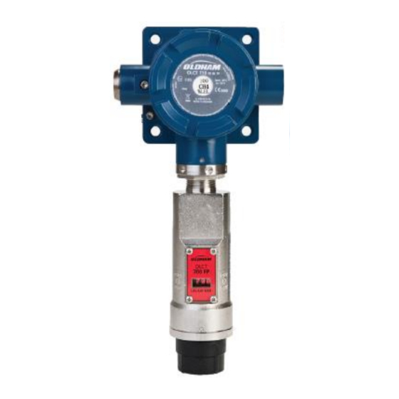
- Page 1 OLCT 700/710 TP 700 TP Series Instruction Manual Hydrogen Sulfide Detector Solid State Sensor OLCT 700 OLCT 710 Part Number: NP700TPIMEN Revision: C.1 The Fixed Gas Detection Experts...
- Page 2 All rights reserved. No reproduction of all or part of this document, in any form, is permitted without the written consent of Oldham S.A.S. All of the information that is provided in this document is accurate to the best of our knowledge.
-
Page 3: Table Of Contents
OLCT 700/710 TP Table of Contents Introduction ............................1 1.1 Description ............................1 1.2 Modular Mechanical Design ......................2 1.3 Plug-in Replaceable Sensor ......................3 Installation ............................. 5 2.1 ATEX Operational Guidelines for Safe Use ................5 2.2 Functional Safety (SIL 2) ......................6 2.3 Detector Placement ........................ - Page 4 OLCT 700/710 TP Table of Figures Figure 1: Detector Assembly Breakaway ......................2 Figure 2: Detector Assembly Front View ......................2 Figure 3: Vue de face de l’OLCT 710 ........................3 Figure 4: OLCT 700/710 TP Plug-in Sensor Cell ....................3 Figure 5: ATEX Approval Label ..........................
- Page 5 Limitation of Reliability ▪ OLDHAM shall not be held responsible for any damage to the equipment or for any physical injury or death resulting in whole or in part from the inappropriate use, installation, or storage of the equipment, which is the result of not complying with the instructions and warnings, and/or with the standards and regulations in force.
- Page 6 OLCT 700/710 TP This page has been left blank intentionally OLCT 700/710 TP...
-
Page 7: Introduction
OLCT 700/710 TP 1. Introduction 1.1 Description Oldham OLCT 700 TP hydrogen sulfide gas transmitters are non-intrusive “Smart” detectors designed to detect and monitor S in air. Ranges of detection are 0-20ppm, 0-50ppm, 0- 100ppm, and 0-200ppm. The detector features an LED display of current reading, fault and calibration status. -
Page 8: Modular Mechanical Design
O-Ring’s) 4) Splash Guard NOTE: All metal components are constructed from electro polished 316 Stainless Steel in order to maximize corrosion resistance in harsh environments. LED Display detcon inc. OLDHAM OLCT MODEL Program Switch #1 TP-700 Program Switch #2... -
Page 9: Plug-In Replaceable Sensor
It can be accessed and replaced in the field very easily by releasing the locking screw and unthreading the housing bottom. The Oldham solid state H sensor has an infinite shelf life and is supported by a 5 year, industry-leading warranty. - Page 10 OLCT 700/710 TP This page has been left blank intentionally Page 4 of 45 Rev. C.1 OLCT 700/710 TP Instruction Manual...
-
Page 11: Installation
OLCT 700/710 TP 2. Installation 2.1 ATEX Operational Guidelines for Safe Use OLCT 700/710 conforms to the requirements of European Directive ATEX 94/9/CE relating to explosive Gas atmospheres. The information given in the following sections should be respected and taken into account by the manager of the site where the equipment is installed. -
Page 12: Functional Safety (Sil 2)
OLCT 700/710 TP 2.2 Functional Safety (SIL 2) Refer to safety user manual NP700TPSMEN 2.3 Detector Placement Selection of detector location is critical to the overall safe performance of the product. Six factors play an important role in selection of detector locations: (1) Density of the gas to be detected (2) Most probable leak sources within the industrial process (3) Ventilation or prevailing wind conditions... -
Page 13: Sensor Contaminants And Interference
Isopropanol Ethanol NOTE: The Oldham MOS Sensor can be damaged to the point of non-functioning if the unit is left off power and in the presence normal air levels of moisture for periods exceeding 8 hours. NOTE: Always protect the sensor with the Oldham Sealing Cap and a fresh desiccant packet when the detector is powered off, this will avoid permanent sensor damage and help preserve the span calibration. -
Page 14: Mounting Installation
Figure 6: Outline and Mounting Dimensions When mounting on a pole, secure the Junction Box to a suitable mounting plate and attach the mounting plate to the pole using U-Bolts (Pole-Mounting brackets for Oldham J-box accessories are available separately). Page 8 of 45 Rev. -
Page 15: Electrical Installation
Figure 7: Typical Installation NOTE: The Oldham Warranty does not cover water damage resulting from water leaking into the enclosure. However, since the electronics are 100% epoxy encapsulated, only the wire terminations could get wet. Moisture could cause abnormal operation and possibly corrosion to the terminal connections, but permanent damage to the detector would not be expected. -
Page 16: Field Wiring
Modbus™ RS-485 A (+), and B (-). Maximum wire length between detector and 24VDC source is shown in the Table below. Maximum wire size for termination in the Oldham J-Box accessory is 14 gauge. Max loop load resistance between green and black wire (analog signal output) is 500 ohms. Minimum loop load resistance between green and black wire is 100 ohms. - Page 17 OLCT 700/710 TP 3 – Arrange the braid as shown in the picture. Avoid creating "pigtails" 4 - Insert the part back into the OLCT 710 2.7.2 Terminal Connections CAUTION: Do not apply System power to the detector until all wiring is properly terminated and openings are properly closed.
-
Page 18: Initial Start Up
OLCT 700/710 TP Customer Supplied Wiring (In) Customer Explosion Supplied Wiring Proof Power from and 4-20mA Junction Box (Out to next Device) out to Control Device A(+) A(+) B(-) B(-) Modbus RS-485 to Modbus RS-485 to next Device Host Control Device Install a 100-250 Ohm resistor if the 4-20mA output is not used... - Page 19 Remove test gas and observe that the display decreases to “0”. Initial operational tests are complete. Oldham H2S gas detectors are factory calibrated prior to shipment, and should not require significant adjustment on start up. However, it is recommended that a complete calibration test and adjustment be performed 16 to 24 hours after power-up.
- Page 20 OLCT 700/710 TP Page 14 of 45 Rev. C.1 OLCT 700/710 TP Instruction Manual...
-
Page 21: Operation
The momentary contact is generally used to move between menu items and to modify set-point values. Arrows (◄ and ►) are used on the LED display to indicate when the magnetic switches are activated. LED Display detcon inc. OLDHAM OLCT MODEL TP-700 Program Switch #1... -
Page 22: Operator Interface
OLCT 700/710 TP 3.2 Operator Interface The operating interface is menu-driven via the two magnetic (PGM1 and PGM2) program switches located under the target marks of the detector housing. The menu list consists of three major items that include sub-menus as indicated below (refer to the complete Software Flow Chart in Figure 11). Normal Operation Current Reading and Fault Status Calibration Mode... -
Page 23: Normal Operation
OLCT 700/710 TP Software Flowchart Normal Operation Exit PGM1 (3) PGM1 (3) PGM2 (3) PGM2 (10) Calibration Mode (Auto Span) View Sensor Status Auto Time-Out PGM1/2 (M) Set AutoSpan Level Set Range Set Serial ID PGM1/2 (3) AutoTime-out Auto Time-Out Auto Time-Out PGM1/2 (M) PGM1/2 (M) - Page 24 200 to 500cc/min. NOTE 3: Span gas bottles contain 0% humidity and this ultra-low humidity condition will cause inaccurate readings when used to calibrate a detector. To prevent this error, Oldham prescribes the use of a 24” flexible In-Line Humidifying Tube.
-
Page 25: Program Mode
OLCT 700/710 TP Assuming acceptable sensor signal change, after 3 minutes the reading will auto-adjust to the programmed AutoSpan level. During the next 30 seconds, the AutoSpan sequence checks the sensor for acceptable reading stability. If the sensor fails the stability check, the reading is re-adjusted back to the AutoSpan level and the cycle repeats until the stability check is passed. - Page 26 OLCT 700/710 TP Set Range Set Serial ID Set Heater Power Signal Output Check Restore Default Settings 3.5.1 Navigating Program Mode From Normal Operation, enter Program Mode by holding the magnet over PGM2 for 4 seconds (until the displays starts to scroll “View Sensor Status”). Note, the “◄” prompt will show that the magnetic switch is activated during the 4 second hold period.
- Page 27 OLCT 700/710 TP Raw Sensor Resistance The menu item appears as: “Resistance XXXXX” mA Output The menu item appears as: “mA Output XX.XX mA” Input Voltage Supply The menu item appears as: “Voltage XX.X VDC” Operating Temperature The menu item appears as: “Temp XX C” When the status list sequence is complete, the OLCT 700/710 will revert to the “View Sensor Status”...
- Page 28 OLCT 700/710 TP 3.5.5 Set Serial ID Oldham OLCT 700/710 TP detectors can be polled serially via RS-485 Modbus™ RTU. Refer to Section 4.0 for details on using the Modbus™ output feature. Set Serial ID is used to set the Modbus™ serial ID address. It is adjustable from 01 to 256 in hexadecimal format (01-FF hex).
- Page 29 OLCT 700/710 TP 3.5.7 Signal Output Check Signal Output Check provides a simulated 4-20mA output and RS-485 Modbus™ output. This simulation allows the user to conveniently perform a functional system check of their entire safety system. This signal output simulation also aids the user in performing troubleshooting of signal wiring problems. From the “Signal Output Check”...
-
Page 30: Program Features
OLCT 700/710 TP 3.6 Program Features Oldham OLCT 700/710 TP H S gas detectors incorporate a comprehensive set of diagnostic features to achieve Fail-Safe Operation. These Operational features and Failsafe Diagnostic features are detailed below. 3.6.1 Operational Features Over-Range When gas greater than the full-scale range is detected, the OLCT 700/710 display will continuously flash the full-scale reading (20, 50, 100ppm, 200ppm). - Page 31 OLCT 700/710 TP Stability Fault - AutoSpan If the sensor fails the signal stability criteria during AutoSpan sequence (Section 3.4), the “Stability Fault” will be declared. A “Stability Fault” will cause a “Fault Detected” message to scroll once a minute on the display and drop the mA output to 0mA.
- Page 32 OLCT 700/710 TP Temperature Fault If the OLCT 700/710 is currently reporting an ambient temperature that is outside of the –40°C to +75°C range, a “Temperature Fault” is declared. A “Temperature Fault” will cause the “Fault Detected” message to scroll once a minute on the display. The Modbus™ fault register bit for Temperature Fault will be set and will not clear until the fault condition has been cleared.
-
Page 33: Rs-485 Modbus™ Protocol
OLCT 700/710 TP 4. RS-485 Modbus™ Protocol OLCT 700/710 gas detectors feature Modbus™ compatible communications protocol and are addressable via the program mode. Communication is two wire, half duplex 485, 9600 baud, 8 data bits, 1 stop bit, no parity, with the detector set up as a slave device. A master controller up to 1200 meters (4000 feet) away can theoretically poll up to 256 different detectors. -
Page 34: Table 4: Modbus™ Special Registers
OLCT 700/710 TP Content Description Content Definition Value Meaning Range 40015 Calibration Status 0x0000 Idle 0x0001 Zero Calibration Started 0x0002 Span Calibration Started 0x0003 Span Set 0x0004 Span Calibration Unsuccessful 40015 Calibration Enable 0x0001 Set Zero 0x0002 Set Span 0x0008 Signal simulation mode 0x0009 Set OLCT 700/710 FP Bridge Voltage... -
Page 35: Service And Maintenance
Test results should be recorded and reviewed to determine a suitable calibration interval; however, it must not exceed one year. The general manager should put safety procedures in place on-site. OLDHAM cannot be held responsible for their enforcement. 5.2 Visual Inspection The Detector should be inspected annually. - Page 36 OLCT 700/710 TP a) Remove power to OLCT 700/710 TP detector by lifting the + 24VDC wire in J-Box. NOTE: It is necessary to remove power while changing the plug-in H S sensor in order to maintain area classification. b) Use a M1.5 Allen wrench to release the locking setscrew that locks the ITM and bottom housing together (One turn will suffice - Do not remove setscrew completely).
-
Page 37: Troubleshooting Guide
OLCT 700/710 TP 6. Troubleshooting Guide Refer to the list of Failsafe Diagnostic features listed in Section 3.6 for additional reference in troubleshooting activities. Listed below are some typical trouble conditions and their probable cause and resolution path. Figure 13: Sensor PCB Open Heater Probable Cause: Plug-in sensor has failed •... - Page 38 Check for obstructions through stainless flame arrestor (including being wet, blocked, or corroded). • Evaluate area for presence of any contaminating gases as listed in Section 2.4. • Note the sensor’s serial # and report repetitive problems to Oldham’s Repair Department. • Replace plug-in H S sensor. Unstable Output/ Sudden spiking Possible Causes: Unstable power supply, inadequate grounding, or inadequate RFI protection.
- Page 39 • Swap with new ITM to determine if the ITM’s 4-20mA output circuit is faulty. • If the 4-20mA current loop is still out of tolerance, contact Oldham’s Technical Support at support@oldhamgas.com. No Communication - RS-485 Modbus™ If detector has a normal reading with no Faults displayed and the Modbus™ is not communicating.
- Page 40 • repair activities: r2@oldhamgas.com All Technical Service and Repair activities should be handled by the Oldham Service Department via phone, fax or email at contact information given above. RMA numbers should be obtained from the Oldham Service Department prior to equipment being returned. For on-line technical service, customers should have ready the model number, part number, and serial number of product(s) in question.
-
Page 41: Appendix
OLCT 700/710 TP 7. Appendix 7.1 Specifications Sensor Type: Continuous diffusion/adsorption type CHEMFET Solid State MOS type True plug-in replaceable type Sensor Life: 5-10 years typical Measuring Ranges: 0-20ppm, 0-50ppm, 0-100ppm Accuracy/ Repeatability: ± 10% of reading or ± 2ppm (whichever is greater) Response Time: T50 <... - Page 42 OLCT 700/710 TP Mechanical Specifications Dimensions : OLCT 700 7"H x 2.2" Dia.; 178mmH x 65mm Dia. OLCT 710 13.74"H x 5.0"W x 5.12"D; 349mmH x 127mmW x 130mmD Weight: 2.5 lbs; 1.14 kg (OLCT 700 only) 7.4 lbs; 3.36 kg (OLCT 710 w/aluminum j-box) 16.4 lbs;...
-
Page 43: Spare Parts, Detector Accessories, Calibration Equipment
OLCT 700/710 TP 7.2 Spare Parts, Detector Accessories, Calibration Equipment Part Number Spare Parts DET-927-015500-100 OLCT 700/710 TP Intelligent Transmitter Module (ITM) DET-602-003280-000 OLCT 700/710 TP Housing Bottom Assembly (includes Flame Arrestor) DET-370-010000-700 Replacement Plug-in H S sensor DET-500-003087-100 Transient Protection PCA Detector Accessories DET-613-120000-700 Detector Splashguard with integral Cal-Port... -
Page 44: Olct 700710 Tp Drawings
OLCT 700/710 TP 7.3 OLCT 700710 TP Drawings Page 38 of 45 Rev. C.1 OLCT 700/710 TP Instruction Manual... - Page 45 OLCT 700/710 TP Ground Ground OLCT 710 TP Series Dimensional OLCT 700/710 TP Instruction Manual Rev. C.1 Page 39 of 45...
- Page 46 OLCT 700/710 TP Page 40 of 45 Rev. C.1 OLCT 700/710 TP Instruction Manual...
-
Page 47: Ec Declaration Of Conformity
OLCT 700/710 TP 8. EU Declaration of conformity OLCT 700/710 TP Instruction Manual Rev. C.1 Page 41 of 45... - Page 48 OLCT 700/710 TP Page 42 of 45 Rev. C.1 OLCT 700/710 TP Instruction Manual...
-
Page 49: Revision Log
OLCT 700/710 TP 9. Revision Log Revision Date (dd/mm/yyyy) Changes made Approval 30/09/2014 Release 18/06/2015 Addition of the OLCT 710 29/09/2015 EC Declaration Update 01/03/2016 Removal of ¾ NPT entry types 20/04/2016 EU Declaration Update 11/02/2019 Calibration mode correction (chap. 3.3) OLCT 700/710 TP Instruction Manual Rev. - Page 50 OLCT 700/710 TP This page has been left blank intentionally Page 44 of 45 Rev. C.1 OLCT 700/710 TP Instruction Manual...
- Page 51 OLCT 700/710 TP This page has been left blank intentionally OLCT 700/710 TP Instruction Manual Rev. C.1 Page 45 of 45...
- Page 52 The Fixed Gas Detection Experts EUROPEAN PLANT AND OFFICES Z.I. Est – rue Orfila CS 20417 – 62027 Arras Cedex FRANCE Tel: +33 (0)3 21 60 80 80 – Fax: +33 (0)3 21 60 80 00 Website: https://gasdetection.3m.com contact: gasandflamedetection@mmm.com EUROPE AMERICAS ASIA PACIFIC...
Need help?
Do you have a question about the 700 TP Series and is the answer not in the manual?
Questions and answers