Table of Contents
Advertisement
Quick Links
Download this manual
See also:
Technical Manual
Advertisement
Table of Contents

Related Manuals for Oldham olct ir


Summary of Contents for Oldham olct ir
- Page 1 TRANSMITTER DETECTORS FOR EXPLOSIVE GASES TECHNICAL MANUAL Ref.: CD00004 Code: 06_MT_OLCTIR_GB_24_11_06...
- Page 2 ISC/OLDHAM , even if it is involved in the sale of ISC/OLDHAM products. * ISC/OLDHAM cannot be held responsible for direct or indirect damage or be required to pay direct or indirect compensation resulting from the sale or use of any of its products IF THESE PRODUCTS HAVE NOT BEEN DEFINED AND CHOSEN BY ISC/OLDHAM FOR THEIR SPECIFIC USE.
- Page 3 Earth screw Fastening lug Figure 1 " " " " Cable gland, M20 (for armoured or non-armoured cable)
- Page 4 REF. QTY NAME OFSA REF ANTI-SPLASH COVER 6124954 O-RING DIA. 65 x 3 6136242 LOCKING NUT, M5 6903376 "E" ENCLOSURE COVER 6123575 Option: non- CABLE GLAND, M20, ARMOURED CABLE 6343489 armoured cable CABLE GLAND, M20, NON-ARMOURED CABLE 6343493 gland, ref 6343493 EEx 2-PIN TERMINAL BLOCK 6152989 O-RING DIA.
- Page 5 ANTI-SPLASH COVER 6313862 O-RING, DIA. 66 x 3 6136100 LOCKING NUT M5 6903376...
- Page 6 Thread: M25, pitch 1.5 Earth screw...
- Page 7 Check LED Magnetic receiver OLCT IR connections Output signal in mA (terminal 1 Iout of ISC/OLDHAM central units) +24VDC Iout Power supply 0 V (terminal 2 of ISC/OLDHAM central units) Power supply + (terminal 3 of +24VDC ISC/OLDHAM central units)
- Page 8 Earth screw Fastening lug GAS INLET AND OUTLET GAS CIRCULATION /M25 Cable gland, M20 HEAD...
- Page 9 Thread: M25, pitch: 1.5 Earth screw...
- Page 10 + 24V DC power supply (terminal 3 of ISC/OLDHAM central units) (service: output not used) EEx "e" compartment Earth screw Figure 8 OLCT IR M25 version Wiring Thread M25, pitch 1.5 > or = 10 mm 1 kO resistor supplied and wired by ISC/OLDHAM EEx "d"...
- Page 11 Bracket : 6132380...
-
Page 12: Table Of Contents
......23 8. MARKING: ..................................24 8.1. For a detector of the type OLCT IR M25 or other, screw-on version: ......24 8.2. For a detector of the type OLCT IR "E": ................24 9. CERTIFICATE OF APPROVAL ........................25... -
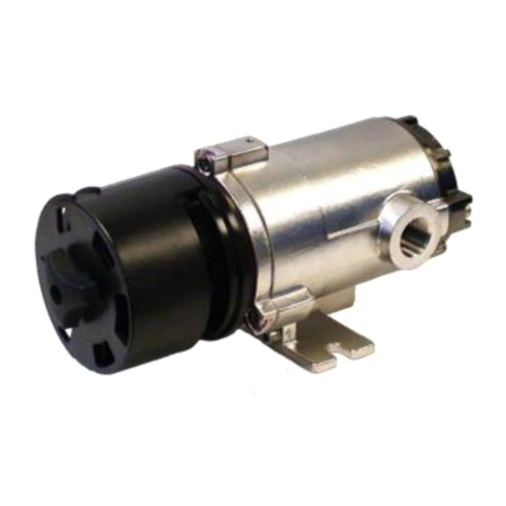
Page 13: Presentation
It uses a direct current power supply and delivers a standardised 4-20 mA current proportional to the measured gas concentration. The "E" version of the OLCT IR has a local calibration device allowing it to be calibrated in an ATEX zone without opening the case. -
Page 14: Technical Characteristics
0 to 99% relative humidity (without condensation) Pressure effect Measurement: partial pressure In the interest of continually improving its products, ISC/OLDHAM reserves the right to modify the specifications given in this document at any time. (2) Most organic compounds containing C-H bonds (3) Hydrogen is not detected. -
Page 15: Interference Levels Of Common Gases On The Olct Ir Ch And Hc
: an output signal of 20 mA is equal to 100% LEL CH or 20 % LEL C (i.e. a factor of 5), • On an OLCT IR HC: an output signal of 6.4 mA is equal to 100% LEL CH or 14 % LEL C (i.e. a factor of 7), •... -
Page 16: Installation
Check the overall dimensions of the detector in situ: see Figures 1 and 4. OLCT IR E version (Figure 1) is designed for fastening to a vertical support such as a wall, etc. If it is fastened to a horizontal support, the adaptor bracket, ref. 6132380 must be used (see Figure 9). -
Page 17: Electrical Installation
Refit the protective cover correctly Connect the sensor body to the earth (Fig. 01). 3.3.2. OLCT IR M25 or other: Once the sensor has been mechanically fastened to a connection system, connect the 4 active wires to the system terminal block, checking polarity as per Figure 08 and ensuring that the sensor body is earthed via the earth screw (Figure 01). -
Page 18: Periodic Maintenance
Use the test cover to inject a standard reference gas (at 2 l/minute) and check the measurement or triggering of alarms (note: without the test cover, the measurement may be underestimated (if wind > 20 kph) 5.4. Calibration procedure for OLCT IR "E" version: Ø Equipment required: Gas calibration kit (bottle of standard reference gas and its accessories) A magnetic to control the maintenance menu and validate the settings. - Page 19 I out: 2 mA continuation LED: Moderate flash sensitivity setting procedure (inject the amount of standard reference gas indicated on the OLCT IR) Note: Waiting time for the value to stabilise ~ 90 s Exit from with zero NO =...
-
Page 20: Calibration Procedure For Olct Ir M25 Or Other
The time between each sweep of the magnet must not exceed 10 minutes; otherwise the procedure will be aborted (return to normal operation). 5.5. Calibration procedure for OLCT IR M25 or other: The sensor cannot be calibrated locally. Zero and sensitivity setting must be carried out from the connected measuring unit (see specific instructions) -
Page 21: List Of Options And References
6.1. LIST OF ACCESSORIES Accessories References Gas circulation head / Calibration pipe 6313863 Test hood 6313829 Calibration magnet 6155651 SHIELD (TO PROTECT AGAINST WEATHER 6124976 AND SOLAR RADIATION) Fastening bracket 6132380 Spare parts References Anti-splash cover 6313862 Connection terminal protective cover (E version) 6123575 Insect screen 6124894... -
Page 22: Special Instructions For Use In Explosive Atmospheres
8 mm of thread with a minimum of 5 threads biting. Cable inlet on OLCT IR E: the cable inlet must have a protection factor of IP 66 as per EN 60 529 and must be appropriate for the operating temperature. -
Page 23: Marking
8.1. For a detector of the type OLCT IR M25 or other, screw-on version: The marking must appear on a glued label or by engraving on the detector. The marking must include the following information: ISC/OLDHAM Arras CE0080 OLCT IR …...
Need help?
Do you have a question about the olct ir and is the answer not in the manual?
Questions and answers