Table of Contents
Advertisement
Quick Links
Advertisement
Table of Contents

Related Manuals for Oldham olct 80


Summary of Contents for Oldham olct 80
- Page 1 TECHNICAL MANUAL Ref.: CD00004 Code: 06_MT_OLCT80_GB_24_11_06...
- Page 2 ISC/OLDHAM , even if it is involved in the sale of ISC/OLDHAM products. * ISC/OLDHAM cannot be held responsible for direct or indirect damage or be required to pay direct or indirect compensation resulting from the sale or use of any of its products IF THESE PRODUCTS HAVE NOT BEEN DEFINED AND CHOSEN BY ISC/OLDHAM FOR THEIR SPECIFIC USE.
- Page 3 Figure 1: Electrical connections, transmitter connected to an ISC/OLDHAM central unit. The contact positions correspond to "sensor de-energerised" (volt free relay) fault relay NO NF C 4 -------- 20 mA Alarm 2 relay NO NF C IN 1 IN 2...
- Page 4 Figure 1b: Electrical connections, stand-alone transmitter The contact positions correspond to "sensor de-energerised" (no potential on contacts) Disturbance relay NO NF C 4 -------- 20 mA Alarm 2 relay NO NF C IN 1 IN 2 rel 2 S E S E NO NF C Alarm 1 relay rel 1...
- Page 5 Earth connection M44, pitch of 1 Possible mounting TITLE OVERALL DIMENSIONS DRAWING TRANSMITTER OLCT80 AD SCALE IDENTIFICATION NO. DRAWN BY: CHECKED BY: APPROVED BY: Figure 2...
- Page 6 Figure 3 SENSOR OLCT80 + IR SENSOR...
- Page 7 Cable length: 15 m max. M44, pitch of 1 Possible mounting TITLE OVERALL DIMENSIONS DRAWING TRANSMITTER OLCT80 REMOTE SCALE IDENTIFICATION NO. DRAWN BY: CHECKED BY: APPROVED BY: Figure 4...
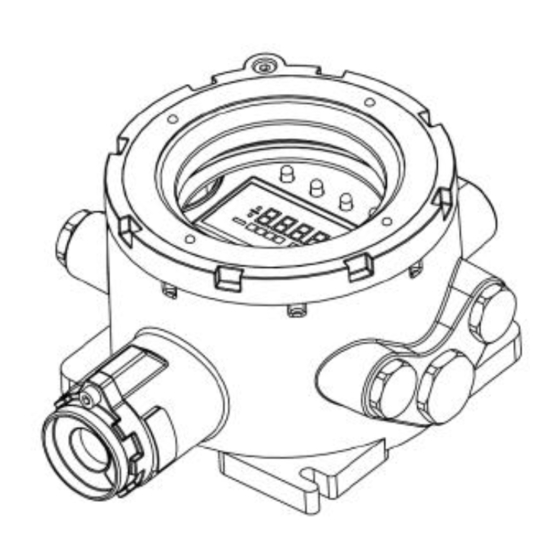
- Page 8 FIGURE 5 Example of an OLCT 80 transmitter fitted with an integrated measuring head and two auxiliary inputs. FIGURE 6 Example of an OLCT 80D transmitter fitted with a remote measuring head and two auxiliary inputs.
- Page 9 Programming of the auxiliary inputs (IN1 and IN2) Connection of a 4 … 20 mA detector (2 wires) IN 1 IN 2 pps7 pps8 pps7 pps8 Connection of a 4 … 20 mA detector (3 wires) IN 1 IN 2 pps7 pps8 pps7...
-
Page 10: Table Of Contents
CONTENTS PRESENTATION ..................12 General....................................12 INSTALLATION..................12 Mechanical installation ................................12 Electrical installation................................12 III. FIRST START-UP ................... 13 Visual information................................13 1.1. At start-up:..................................13 1.2. During normal operation:...............................13 1.3. If a fault occurs:................................13 1.4. Information accessible on the display via the remote control: ................13 OLCT80 transmitter menus..............................14 MAINTENANCE .................. -
Page 11: Presentation
§ The OLCT80 is an analogue/digital transmitter designed for gas detection. It can be installed and addressed in § a network or connected to any acquisition system managing an analogue signal (0 to 20 mA). § The OLCT80 comprises a transmitter (electronic section) and an integrated or remote sensor on the version §... -
Page 12: First Start-Up
Referring to Figure 1 or 1b as the case may be (stand-alone or connected to an ISC/OLDHAM central unit): § Remove the protection cover and the display card to gain access to the connection terminals § Check that the main circuit is correctly programmed for the type of detector connected (see Figure 7) §... -
Page 13: Olct80 Transmitter Menus
The following menus can be accessed and used via the IR20 remote control: OLCT80 MENU SEQUENCE T_green DISPLAY of NORMAL OPERATION FAULT menu Enter key Menu key ACKNOWL menu DISPLAY TIME and PROGRAMMING ACCESS 4-20mA INFO. CALIBRATE TEST DATE CONTROL MENU MENU MANAGEM... - Page 14 PROGRAMMING AND INSTALLATION Channel Alarms and programming Relays programming Relay 3 or Sensor Sensor Input 1 Input 2 Input 1 Input 2 Relay 1 Relay 2 (or head) (or head) Fault On or Off On or Off On or Off Main, display or Main, display or Main, display or...
- Page 15 PROGRAMMING AND INSTALLATION CONT. Change of access Serial link progr. code Speed and slave adress Backlight ON or OFF Change of access Operation mode: code parrallel loop repeater slave adress Communication speed Backlighting ON or OFF Are you sure? Are you sure? Stored in memory Stored in...
- Page 16 CALIBRATION and CHANGE of SENSOR ANA1 ANA2 Change of SENSOR sensor? Change of Zero setting: Zero setting: Choice of sensor? standard gas Zero Sensitivity Sensitivity measurement: setting setting Sensitivity Are you sure? Are you sure? measurement Stored in Stored in memory memory Are you sure?
-
Page 17: Maintenance
Caution: The actions described in this paragraph may affect the reliability of detection and must only be carried out by authorised and trained personnel. Gas detection instruments are potential life -saving devices. Recognizing this fact, Industrial Scientific Corporation recommends that a functional “bump” test be performed on every fixed gas-monitoring instruments as part of a regular maintenance program. -
Page 18: Replacing A Sensor Block (All Versions)
When? § When its performance deteriorates or calibration is impossible, § During preventive maintenance How? § Switch off the measurement channel concerned § Remove the sensor block to be replaced § Replace it with a new, pre -calibrated block § Start up the channel, run the sensor replacement menu and check that it operates correctly §... -
Page 19: Intrinsically-Safe Sensor Blocks
NAME OFSA REF INTRINSICALLY-SAFE SENSOR BLOCKS SENSOR BLOCK, OLCT20 SI CO – 100 6313711 CO – 300 6313712 CO – 1000 ppm 6313713 CO/H2– 1000 ppm 6313694 6313716 SENSOR BLOCK, OLCT20 SI H2S – 30 6313717 H2S – 100 6313718 H2S –... -
Page 20: List Of Accessories
SENSOR BLOCK, OLCT20 SI ETO - 30 ppm 6313746 SENSOR BLOCK, OLCT20 SI SiH4 - 50 ppm 6313747 6313748 SENSOR BLOCK, OLCT20 SI O2 – 30 %vol TOOL KIT 6145856 6147870 GAS INTAKE DEVICE Standard model for O2, CO, H2S, H2 6331137 Model for explosive or special gases NO2, SO2, CL2, HCL, HCN, HF, NH3, ETO, O3, CLO2, PH3, NO etc. -
Page 21: List Of Spare Parts
CAUTION: Spare parts must always be guaranteed original ISC/OLDHAM parts. The use of any other parts could call into question the safety of the equipment. Spare parts Reference Assembled cover without manufacturer's plate 6 323 636 6 343 490 Cable gland kit for armoured cable, M25... -
Page 22: Marking And Special Instructions For Use Of The Olct
Zones of use: Version OLCT 80 d : the equipment is authorised for use in zones 1, 2, 21 and 22 for ambient temperatures between -25°C and +70°C with a temperature class of T5 / T100°C, or T6 / T85°C. - Page 23 The marking must appear on a glued label or is engraved on the detector. The marking must include the following information: For a type OLCT80d detector: On the case and the detection element if it is remote OLDHAM Arras CE0080 OLCT80d II 2GD IP66 EEx d IIC T5( T100°C) or T6 (T85°C)
-
Page 24: Specifications
- 25 °C to +55 °C ( electronics, see table for detection cells ) Note: Performance levels are reduced at higher temperatures (max. 70°C): Operating temperatures contact us for details. Dimensions See drawings Weight OLCT 80: 3.5 kg Conforms to Directive 94/9/EC, see ATEX ATEX certification paragraph Electromagnetic compatibility Complies with EN 50270... - Page 25 Characteristics and Special Precautions for explosive gas detectors, sensor block 6313385 • The sensors are sensitive to certain products which could desensitise them: silicone emissions in concentrations greater than 10 ppm, chlorinated or sulphurated products in concentrations greater than 100 ppm.
-
Page 26: Remote Control Unit Ir20 - Start-Up And Use
– The IR20 remote control unit is a stand-alone portable device designed for monitoring, setting and maintenance of ISC/OLDHAM gas detection equipment. It features an infrared link allowing the operator to send maintenance orders to the transmitter from a remote location. -
Page 27: Special Instructions For Use In Atex Explosive Atmospheres
Replacement batteries must be identical to the original batteries specified by ISC/OLDHAM. The operating temperature is between -40°C and +70°C. The IR20 remote control unit has the following marking: OLDHAM France 62 Arras CE 0080 IR20 II 2 G... -
Page 28: Binary Mode
The transfer table is as follows: /* measurements */ table_tr_byte[0] = voie[0].mes; table_tr_byte[2] = voie[1].mes; table_tr_byte[4] = voie[2].mes; table_tr_byte[6] = mes_ligne; table_tr_byte[8] = mes_temp_int; table_tr_byte[10] = mes_temp_ext; table_tr_byte[12] = mes_1v2; table_tr_byte[14] = mes_ref; table_tr_byte[16] = taux_usure; /* statuses table_tr_byte[30] = voie[0].etat; table_tr_byte[32] = voie[0].def;...
Need help?
Do you have a question about the olct 80 and is the answer not in the manual?
Questions and answers