Advertisement
Quick Links
*15G06M039000AK*
P/ N: 15G06M039000AK V1.0
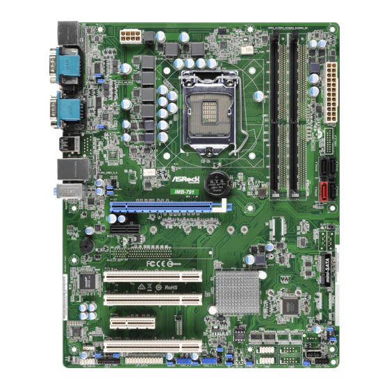
IMB-791
1 : ATX 12V Power Connector
2 : CPU FAN Connector (+12V)
GND
+12V
CPU_FAN_SPEED
FAN_SPEED_CONTROL
3 : DDR4 DIMM Slots (DDR4_A1, DDR4_B1)
4 : 24-pin ATX Power Input Connector
5 : SATA3 Connectors
(SATA3_1 ~ SATA3_4)
USB Power Setting Jumpers
6 : USB2_PWR3 (For USB2_9)
16 : USB2_PWR1 (For USB2_4_5),
USB2_PWR2 (For USB2_6_7)
25 : USB3_PWR1 (For USB3_1_2),
USB3_PWR2 (For USB3_3_4)
1-2 : +5V
2-3 : +5VSB
7 : ATX/AT Mode Jumper (PWR_JP1)
1-2 : AT Mode
2-3 : ATX Mode
8 : Vertical Type A USB 2.0 Port (USB2_9)
9 : System Panel Header
PLED+
PLED-
PWRBTN#
GND
1
GND
RESET#
GND
HDLED-
HDLED+
Jumpers and Headers Setting Guide
PWR_COM1
1
PS2_PWR1
1
PWR_COM2
1
USB 3.0
T: USB1
B: USB2
USB 3.0
Top:
CHA_FAN1
T: USB3
LAN2
B: USB4
LAN_LED3
1
1
LAN_LED4
USB3_PWR1
1
1
USB3_PWR2
PCIE1
PCIE2
BUZZ1
BUZZ2
1
PCI1
PCI2
PCIE4
AUDIO
CODEC
PCI3
SPDIF1
1
JGPIO_SET1
JGPIO_PWR1
1
1
LPT_GPIO1
HD_AUDIO1
1
1
LPC1
Clear CMOS Headers
8
5
10 : CLRMOS2
12 : CLRMOS1
4
1
1-2 : Normal
2-3 : Clear CMOS
11 : COM Port Headers (COM3, 4)
(RS232)
12
24
1
13
COM Port Pin9 PWR Setting Jumpers
13 : PWR_COM3 (For COM Port3)
PWR_COM4 (For COM Port4)
31 : PWR_COM2 (For COM Port2)
34 : PWR_COM1 (For COM Port1)
1-2 : +5V
2-3 : +12V
14 : Chassis Intrusion Headers
(CI1, CI2)
Short : Active Case Open
Open : Normal
15 : USB 2.0 Headers
(USB2_4_5, USB2_6_7)
USB_PWR
P-
P+
GND
1
GND
P+
P-
USB_PWR
CPU_FAN1
CMOS
Industrial
Battery
IMB-791
RoHS
PWR_LOSS1
1
BIOS
ROM
CI2
1
CI1
1
1
PWR_COM3
COM3
1
USB2_4_5
USB2_6_7
USB2_PWR1
USB2_PWR2
PWR_COM4
CLRMOS1
1
1
1
1
1
1
1
COM4
RRXD1
DDTR#1
DDSR#1
CCTS#1
1
COM PWR
RRTS#1
GND
TTXD1
DDCD#1
1
GND
Signal
DUMMY
USB2_PWR3
1
1
PWR_JP1
USB2_9
PLED PWRBTN
CLRMOS2
1
1
HDLED RESET
PANEL1
17 : Printer Port / GPIO
Header (LPT_GPIO1)
Printer Port:
GPIO:
* If you want to use the printer port function, please short pin4 and pin5 on
Digital Input / Output Power Select (JGPIO_PWR1).
18 : Digital Input / Output Power Select
(JGPIOPWR) (JGPIO_PWR1)
1-2 : +12V
1
2-3 : +5V
3-4 : +5V
4-5: GND
19 : LPC Header
1
20 : Digital Input / Output Power Select
(JGPIO_SET1)
1-2 : +5V
2-3 : GND
Advertisement

Related Manuals for ASROCK IMB-791


Summary of Contents for ASROCK IMB-791
- Page 1 *15G06M039000AK* P/ N: 15G06M039000AK V1.0 Jumpers and Headers Setting Guide IMB-791 CPU_FAN1 PWR_COM1 PS2_PWR1 PWR_COM2 USB 3.0 T: USB1 B: USB2 USB 3.0 Top: CHA_FAN1 T: USB3 LAN2 B: USB4 LAN_LED3 CMOS Industrial LAN_LED4 Battery USB3_PWR1 IMB-791 USB3_PWR2 PCIE1 PCIE2...
- Page 2 PS2_PWR1 PWR_COM2 USB 3.0 T: USB1 B: USB2 USB 3.0 Top: CHA_FAN1 T: USB3 LAN2 B: USB4 LAN_LED3 CMOS Industrial LAN_LED4 Battery USB3_PWR1 IMB-791 USB3_PWR2 PCIE1 PCIE2 BUZZ1 BUZZ2 PCI1 RoHS PCI2 PWR_LOSS1 PCIE4 USB2_PWR3 AUDIO BIOS CODEC PWR_JP1 PCI3...
Need help?
Do you have a question about the IMB-791 and is the answer not in the manual?
Questions and answers