Table of Contents
Advertisement
Quick Links
Advertisement
Table of Contents

Related Manuals for Endace DAG 3.7D

Summary of Contents for Endace DAG 3.7D
- Page 2 EDM01-16: DAG3.7D Card User Guide Published by: ® Endace Measurement Systems Building 7 17 Lambie Drive PO Box 76802 Manukau City 1702 New Zealand Phone: +64 9 262 7260 Fax: +64 9 262 7261 support@endace.com www.endace.com International Locations New Zealand Americas Europe, Middle East &...
- Page 3 EDM01-16: DAG3.7D Card User Guide Protection Against Harmful Interference When present on equipment this manual pertains to, the statement "This device complies with part 15 of the FCC rules" specifies the equipment has been tested and found to comply with the limits for a Class A digital device, pursuant to Part 15 of the Federal Communications Commission [FCC] Rules.
- Page 4 EDM01-16: DAG3.7D Card User Guide...
-
Page 5: Table Of Contents
EDM01-16: DAG3.7D Card User Guide Table of Contents Chapter 1: Introduction Overview Purpose Card Description Card Architecture Extended Functions System Requirements Chapter 2: Installation Introduction DAG Device Driver Inserting the Card Port Connectors Chapter 3: Confidence Testing Introduction Card Sensitivity LED Status LED Display Functions Dagthree Utility... - Page 6 EDM01-16: DAG3.7D Card User Guide ©2006 Version 1: March 2006...
-
Page 7: Chapter 1: Introduction
Chapter 1: Introduction Overview The installation of the Endace DAG 3.7D card on a PC begins with installing the operating system and the Endace software. This is followed by fitting the card and connecting the ports. The characteristics include card architecture, extended functions, and system requirements. -
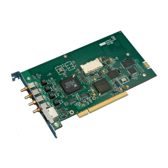
Page 8: Card Description
All packet records are written to host PC memory during capture operations. Serial PDH data is received by the DAG 3.7D card co-axial interfaces, and fed into dual DS3/E3 framer. Network data is then fed to the FPGA which also contains the DUCK timestamp engine. -
Page 9: Extended Functions
The current firmware only supports bit synchronisations HDLC demapping. Extended The functionality of the DAG 3.7D card can be extended in many ways. A physical transmit path is provided on the card so that packet organisation is Functions possible, requiring special firmware images. -
Page 10: System Requirements
EDM01-06: DAG 3.7D Card User Guide System General Requirements The DAG 3.7D card and associated data capture system minimum operating requirements are: • PC, at least Pentium II 400 MHz, Intel 440BX, GX or newer chip set • Minimum of 128 MB RAM •... -
Page 11: Chapter 2: Installation
Installation Introduction A DAG 3.7D card can be installed in any free 3.3V or 5V Bus Mastering PCI slot. The card should be the only device on the PCI bus if possible as the cards make very heavy use of PCI bus data transfer resources. - Page 12 EDM01-06: DAG 3.7D Card User Guide ©2006 Version 1: March 2006...
- Page 13 EDM01-06: DAG 3.7D Card User Guide ©2006 Version 1: March 2006...
-
Page 14: Chapter 3: Confidence Testing
Card Overview Sensitivity The input signal level to the DAG 3.7D card should be within the dynamic range of the receiver. If the input signal power is slightly out of range then an increased bit error rate will be experienced. -
Page 15: Led Status
Not enabled Not enabled LED Display On the DAG 3.7D card LED 8 flashes when a PPS signal is being received, LED 7 flashes when a PPS signal is being outputted. Functions When DS3 signals are applied LEDs 3 and 5 should come on. The status of these LEDs should not change during normal operation of the card. -
Page 16: Card Configurationoptions
EDM01-06: DAG 3.7D Card User Guide Card Configuration Running the command ' alone shows the current configuration. dagthree' Each of the items displayed can be changed as follows: Options set card to normal defaults default (un) set facility Loopback. Should be set to nofcl. -
Page 17: Interface Statistics
EDM01-06: DAG 3.7D Card User Guide Interface Statistics Once the DAG 3.7D card has been configured as expected, the interface statistics should be inspected to see if the card is locked to the data stream. port A dag@endace:~$ dagthree –d0 -asi port B dag@endace:~$ dagthree –d0 –bsi... -
Page 18: Card Capture Session
EDM01-06: DAG 3.7D Card User Guide Card Capture Overview Session The DAG 3.7D card uses the OS3/E3 ATM UNI/PPP physical layer interface device to support capturing of ATM. The card supports the DS3 standard. A successful DAG card capture session is accomplished by checking the receiver ports optical signal levels and checking the card has correctly detected the link. - Page 19 EDM01-06: DAG 3.7D Card User Guide Card Capture Add –f flag Session (cont.) • Add the –f flag to dagld. dag@endace:~$ dagthree –d0 PortA: rx_monitor ds3_m13 nofcl hdlc PortB: rx_monitor ds3_m13 nofcl hdlc packet varlen slen=64 align64 packetA drop=0 packetB drop=0...
-
Page 20: Reporting Problems
EDM01-06: DAG 3.7D Card User Guide Reporting If you have problems with a DAG card or Endace supplied software which you are unable to resolve, please contact Endace Customer Support at Problems support@endace.com. Supplying as much information as possible enables Endace Customer Support to be more effective in their response to you. -
Page 21: Chapter 4: Running Data Capture Software
High Load Overview Performance As the DAG 3.7D card captures packets from the network link, it writes a record for each packet into a large buffer in the host PC’s main memory. Avoiding packet Loss To avoid packet loss, the user application reading the record, such as... - Page 22 EDM01-06: DAG 3.7D Card User Guide High Load Detecting Packet Losses Performance Until some data is read out of the buffer to free some space, any arriving packets subsequently are discarded by the DAG card. Any loss is detected (cont.)
-
Page 23: Chapter 5: Synchronizing Clock Time
Common synchronisation sources include GPS or CDMA (Cellular telephone) time receivers. Endace produces the TDS 2 Time Distribution Server modules and the TDS 6 units that enable multiple DAG cards to be connected to a single GPS or CDMA unit. - Page 24 EDM01-06: DAG 3.7D Card User Guide Configuration Description Tools The DUCK is very flexible, and can be used with or without an external time reference source. It can accept synchronisation from several input sources, and also be made to drive its synchronisation output from one of several sources.
-
Page 25: Configuration Tools
EDM01-06: DAG 3.7D Card User Guide Configuration dag@endace:~$ dagclock –d dag0 Tools (cont.) muxin rs422 muxout none status Synchronised Threshold 596ns Failures 0 Resyncs 0 error Freq -30ppb Phase -60ns Worst Freq 75ppb Worst Phase 104ns crystal Actual 100000028Hz Synthesized 67108864Hz... -
Page 26: Two Cards No Reference
EDM01-06: DAG 3.7D Card User Guide Two Cards No Overview Reference When two DAG cards are used in a single host PC with no reference clock, the cards must be synchronized in some way if timestamps between the two cards are to be compared. For example, if two cards monitor different directions of a single full-duplex link. -
Page 27: Card With Reference
[PPS] signal from external sources. This is derived directly from a reference source, or distributed through the Endace TDS 2 [Time Distribution Server] module which allows two DAG cards to use a single receiver. More cards can be accommodated by daisy-chaining TDS-6 expansion units to the TDS-2 unit, each providing outputs for an additional 6 DAG cards. - Page 28 EDM01-06: DAG 3.7D Card User Guide dag@endace:~$ dagclock –d dag0 muxin rs422 muxout none status Synchronised Threshold 596ns Failures 0 Resyncs 0 error Freq 30ppb Phase -15ns Worst Freq 2092838ppb Worst Phase 33473626ns crystal Actual 100000023Hz Synthesized 67108864Hz input Total 225 Bad 0 Singles Missed 1 Longest...
-
Page 29: Connector Pin-Outs
EDM01-06: DAG 3.7D Card User Guide Connector Pin- Overview outs DAG cards have an 8-pin RJ45 connector with two bi-directional RS422 differential circuits, A and B. The PPS signal is carried on circuit A, and the serial packet is connected to the B circuit. - Page 30 EDM01-06: DAG 3.7D Card User Guide ©2006 Version 1: March 2006...
-
Page 31: Chapter 6: Data Formats
Chapter 6: Data Formats Overview The DAG card produces trace files in the Endace Extensible Record Format (ERF). The ERF consists of a series records. Each record describes one packet. An ERF file consists only of ERF records. There is no special file header. -
Page 32: Pos Hdlc Record
EDM01-06: DAG 3.7D Card User Guide Pos HDLC The Type 1 PoS HDLC Record format is for HDLC data links. For example: Record • Packet over SONET • Point-to-Point Protocol [PPP] over SONET • Frame Relay The record is described below:... -
Page 33: Timestamps
EDM01-06: DAG 3.7D Card User Guide Timestamps The ERF incorporates a hardware generated timestamp of the packet’s arrival. The format of this timestamp is a single little-endian 64-bit fixed point number, representing seconds since midnight on the first of January 1970.
Need help?
Do you have a question about the DAG 3.7D and is the answer not in the manual?
Questions and answers