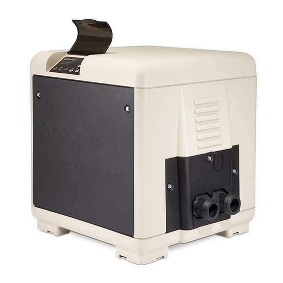
Pentair MASTERTEMP 125 Installation And User Manual

Pentair MASTERTEMP 125 Installation And User Manual

Pool and spa heater

Advertisement

MASTERTEMP
INSTALLATION AND USER'S GUIDE (AUSTRALIA)
FOR YOUR SAFETY - READ BEFORE OPERATING
FOR YOUR SAFETY - This product must be installed and serviced by authorized personnel, qualified in pool/spa
heater installation. Improper installation and/or operation can create carbon monoxide gas and flue gases which can
cause serious injury, property damage, or death. For indoor installations, as an additional measure of safety, Pentair
Water Pool and Spa strongly recommends installation of suitable Carbon Monoxide Detectors in the vicinity of this
appliance and in any adjacent occupied spaces. Improper installation and/or operation will void the warranty.
240 VAC NATURAL GAS/LP GAS
Model MT125 HD
125K (33 kW) with cord
FOR YOUR SAFETY
damage, personal injury or loss of life.
damage, personal injury or death. Installation and service must be performed by a qualified
installer, service agency or the gas supplier.
FOR
YOUR
SAFETY
125 POOL AND SPA HEATER
Natural
Propane
461092
461093
WHAT TO DO IF YOU SMELL GAS
www.pentairpool.com.au - www.pentairpool.com - www.staritepool.com
Rainbow Pool Products
®
PO Box 2388, Mansfield Qld 4122
Telephone STD 61-7-3849 5385
Facsimile STD 61-7-3849 5384
Email: info@rainbowpoolproducts.com.au
Web: www.rainbowpoolproducts.com.au
OWNER:
Retain For
Future
Reference

Advertisement

Table of Contents
loading

Summary of Contents for Pentair MASTERTEMP 125

  • Page 1 Improper installation and/or operation can create carbon monoxide gas and flue gases which can cause serious injury, property damage, or death. For indoor installations, as an additional measure of safety, Pentair Water Pool and Spa strongly recommends installation of suitable Carbon Monoxide Detectors in the vicinity of this appliance and in any adjacent occupied spaces.
  • Page 2 | Code Requirements / References Customer Service If you have questions about ordering Pentair Aquatic Systems replacement parts, and pool products, please use the following contact information. Customer Service and Technical Support, AUS (AEST Time) Phone: 1300 137 344...
  • Page 3: Table Of Contents

    Contents Contents ..................... ii - iii ................................Warnings and Safety Instructions / Consumer Information / General Specifications ................iv - viii Operating the Control Panel ..............................Section 1. Operation Instructions......................Operating Instructions / Basic System Operation ........................... Heater HSI (Hot-Surface Ignition) Lighting/Operation ........................Start-up and Operation / Before You Start ............................
  • Page 4 4) Fuel Type : (LP = Propane gas or NG = Natural gas) HEATER IDENTIFICATION INFORMATION — (HIN) H. I. N. HEATER IDENTIFICATION NUMBER ID DESIGNATOR FOR PENTAIR WATER POOL AND SPA MASTERTEMP™ 125 HEATER Example: NG = NATURAL GAS...
  • Page 5 Warning and Safety Instructions Warning and Safety Instructions IMPORTANT SAFETY INSTRUCTIONS READ AND FOLLOW ALL INSTRUCTIONS SAVE THESE INSTRUCTIONS MasterTemp 125 High Performance Heater ™ ® ® ® ® IMPORTANT NOTICES WARRANTY INFORMATION CAUTION OPERATING THIS HEATER CONTINUOUSLY AT WATER TEMPERATURE BELOW 20° C (68° F). WILL CAUSE HARMFUL CONDENSATION AND WILL DAMAGE THE HEATER AND VOID THE WARRANTY.
  • Page 6 Warnings and Safety Instructions CODE REQUIREMENTS CONSUMER INFORMATION AND SAFETY WARNING Should overheating occur or the gas supply fail to shut off, turn off the manual gas control valve to the heater. Do not use this heater if any part has been under water. Immediately call a qualified service technician to inspect the heater and to replace any part of control system and gas control which has been under water.
  • Page 7 Warning and Safety Instructions CONSUMER INFORMATION AND SAFETY (CONTINUED) WARNING The Consumer Product Safety Commission warns that carbon monoxide is an “invisible killer”. Carbon monoxide is a colorless and odorless gas. GENERAL SPECIFICATIONS NOTICE: minutes with the access door panels removed. NOT be 240 VAC single-phase electric power source.
  • Page 8: Warnings And Safety Instructions / Consumer Information / General Specifications

    Warnings and Safety Instructions WARNINGS AND SAFETY INSTRUCTIONS The MasterTemp 125 CARBON MONOXIDE GAS IS DEADLY DANGER — READ OWNERS MANUAL COMPLETELY BEFORE OPERATING EXCESSIVE CARBON MONOXIDE EXPOSURE CAN CAUSE BRAIN DAMAGE OR DEATH. vents and other openings. WARNING — FOR YOUR SAFETY WARNING —...
  • Page 9 Warning and Safety Instructions viii WARNINGS AND SAFETY INFORMATION (CONTINUED) WARNING — Risk of fire or explosion from incorrect fuel use or faulty fuel conversion. Do not try to run a WARNING — Risk of explosion if unit is installed near propane gas storage. WARNING —...
  • Page 10: Operating The Control Panel

    Operating the Control Panel OPERATING THE CONTROL PANEL Temperature Digital Temperature Up and Down Display System Operation Dual Temperature Heater "OFF" Indicator Lights Controls Switch POOL ON SPA ON HEATER OFF TEMP TEMP TEMP TEMP TEMP TEMP POOL ON SPA ON HEATING SERVICE SYSTEM SERVICE HEATER...
  • Page 11: Section 1. Operation Instructions

    Section 1: Operation Instructions Section 1: Operation Instructions BASIC SYSTEM OPERATION Start pump, make sure the pump is running and is primed, to close the water pressure switch and supply power to heater. Be sure the pool and/or spa is properly filled with water. Follow the Lighting/Operating instructions below. HEATER HSI ELECTRONIC IGNITION LIGHTING/OPERATION FOR YOUR SAFETY: READ BEFORE LIGHTING WARNING...
  • Page 12: Operating Instructions / Basic System Operation

    Section 1: Operation Instructions OPERATING INSTRUCTIONS 1. STOP! 3. Turn off all electric power to the appliance. Turn OFF the Outside Water Pressure Manual Shut-Off Valve (Figure 3.). Switch 4. This appliance does not have a pilot. It is equipped with an ignition device which automatically lights the burner.
  • Page 13: Safety Controls: Air Flow Switch (Afs) / Water Pressure Switch / High Limit Devices

    Section 1: Operation Instructions SAFETY CONTROLS AIR FLOW SWITCH (AFS) air blower (fan) is operating and has been designed to monitor the vacuum (negative) upstream of the ignition module. The ignition module does not operate unless the air pressure switch and all safety switches are closed. WATER PRESSURE SWITCH Air Flow Switch Figure 4.
  • Page 14: Operation Of Ignition Module

    Section 1: Operation Instructions Flame Current SAFETY CONTROLS Diagnostic LED (continued) Check Point 1 Flash - Air Flow Fault 2 Flashes - Flame No Call for Heat OPERATION OF IGNITION MODULE 3 Flashes - Ignition Lockout (see Figure 7), The Ignition Module is microprocessor based and operates on 24VAC supplied by the transformer.
  • Page 15: Section 2. Installation Instructions

    This product must be installed and serviced by a professional service technician, qualified in pool heater installation. Pentair strongly recommends that all vents, pipes and exhaust systems be initially and periodically tested for proper operation. This testing can be accomplished by using a hand-held carbon monoxide meter and/or by consulting with a gas professional.
  • Page 16 Section 2: Installation Instructions PUTTING THE HEATER INTO SERVICE If the heater is installed below the level of the pool, or more than 0.6 meters (2 feet) above pool level, the pressure switch the front of this manual. Check for proper operation of the heater by following the steps under, see page 11 “OPERATION SPECIFICATIONS (DIMENSIONS IN CENTIMETERS AND INCHES) Installations.
  • Page 17 Section 2: Installation Instructions PLUMBING CONNECTIONS Figure 12. The MasterTemp 125 heater has the capability of direct schedule 40 PVC plumbing connections. A set of bulkhead conformity with Pentair’s recommended PVC plumbing Figure 12 for plumbing connections. CAUTION HEATER PUMP...
  • Page 18: Valves

    Section 2: Installation Instructions VALVES When any equipment is located below the surface of the pool or spa, valves should be placed in the circulation piping NOT sanitize the pool by putting chlorine tablets or sticks into the skimmer(s). When the pump is off, this will cause a high concentration of chlorine to enter the heater, which could cause corrosion damage to the heat exchanger.
  • Page 19 Section 2: Installation Instructions GAS CONNECTIONS GAS LINE INSTALLATIONS The gas supply must be installed in accordance with the and all applicable local Gas Installation Code, AS/NZS.5601.1 codes. Before installing the gas line, be sure to check which gas the heater has been designed to burn. This is important because different types of gas require different gas pipe sizes.
  • Page 20 10 | Section 2: Installation Instructions TESTING GAS LEAKS AND GAS PRESSURE Before operating THE MASTERTEMP HEATER IS INTENDED FOR INSTALLATION WITH A METERED GAS PRESSURE REGULATOR. the heater, the heater and its gas connections must be leak tested. Test all gas connections for leaks with soapy water.
  • Page 21 Section 2: Installation Instructions | 11 OUTDOOR HEATER INSTALLATION (AUSTRALIA) The following information is for heaters located outdoors, using the built-in stackless venting system. WARNING CARBON MONOXIDE GAS IS DEADLY – Exhaust from this pool heater contains carbon monoxide, a dangerous, poisonous gas you cannot see or smell.
  • Page 22 Section 2: Installation Instructions 12 | HEATER CLEARANCES – OUTDOOR IMPORTANT! ° 1 meter (3 ft.) or more If the heater is located under a roof overhang, there must be at least 1 meter (3 feet) of clearance between the bottom of the overhang and the top of the heater exhaust vent, see Figure 19.
  • Page 23 Section 2: Installation Instructions | 13 INDOOR VENTING — General Requirements NOTE: REMOVE OR COVER “OUTDOOR ONLY” LABEL LOCATED ON HEATER OUTSIDE PANEL WITH “INDOOR INSTALLATION” LABEL (P/N 474275) INCLUDED IN ACCESSORY BAG (P/N 473607). INDOOR INSTALLATION (SEE INSTALLATION GUIDE FOR CORRECT PLACEMENT OF THIS LABEL) DO NOT vent gas temperature less than 204°...
  • Page 24 30 cm (12 in) of the ceiling, the other Pentair does not recommend codes that may apply. These openings shall directly, or through duct, connect to outdoor air.
  • Page 25 To connect a double wall metal gas vent to the heater, order the Table 6 determine allowable vent sizes for your heater. 1. STEP 1: See Table 6, to determine allowable vent sizes for the MasterTemp 125 heater. Clean and RTV This Surface Combustion Metal Flue Collar Part No.
  • Page 26 14.67m (48.1 ft.) See previous page for STEP 1 - See Table 6 (page 15), to determine allowable vent sizes for the MasterTemp 125 heater. 2. Install the metal Flue Collar in the Vent Body of the heater (located under the outside vent cover). Fasten the metal Flue Collar to the Vent Body with two #10 sheet metal screws.
  • Page 27 Section 2: Installation Instructions | 17 WARNING! Risk of fire or asphyxiation if vent is not assembled according to manufacturer’s instructions or if vent parts from different manufacturers are mixed. Vent parts from different manufacturers ARE NOT interchangeable. Mixing parts from more than one manufacturer may cause leaks or damage to vent. When assembling a vent, pick one manufacturer and be sure that all vent parts come from that manufacturer and are specified by the manufacturer for your system.
  • Page 28 Section 2: Installation Instructions 18 | HORIZONTAL OR VERTICAL VENTING - USING SINGLE-WALL STAINLESS GAS VENT (SEE FIGURES 26, 27, & 28) Vent the heater either horizontally or vertically using an optional vent adapter of the 150 mm (6 in) or 102 mm (4 in) special gas approved stainless steel vent pipes.
  • Page 29 Metallic: 1. Order an optional appliance adapter kit, (Pentair offers optional appliance adapter kits, call Customer Service) 2. Remove the outside vent cover. 3. Install the Appliance Adapter in the Vent Body of the heater (located under the outside Vent Cover). Before connecting the Appliance Adapter to the Vent Body, wet a clean cloth or paper towel with isopropyl alcohol (rubbing alcohol) and vigorously wipe the socket of the Vent Body.
  • Page 30 Figure 15. Section 2: Installation Instructions 20 | Chimney or Gas Vent Vent Cap and Riser Furnished by Installer Chimney or Gas Vent Vent Cap and Riser Furnished by Installer Outlet Air Opening Outlet Air Opening Side Inlet Air Opening Wall Vent Heater Side...
  • Page 31 Section 2: Installation Instructions | 21 Allow at least 1 M (3 ft) vertical clearance over vent Metal Special termination when terminating under an overhang or Support Gas Vent deck. Avoid corners or alcoves where snow or wind weight requires of pipe could have an effect.
  • Page 32 Section 2: Installation Instructions 22 | NOTE: KEEP A 150 CM (6 IN) MINIMUM CLEARANCE BETWEEN THE VENT PIPE AND COMBUSTIBLE SURFACES. FOLLOW THE VENT MANUFACTURER’S INSTRUCTIONS AND CODE REQUIREMENTS. 90° bend. NOTE After installation, installer must check for correct and safe operation of the heater. Corrosive Vapors and Possible Causes (see Table 5 on page 14).
  • Page 33 Section 2: Installation Instructions | 23 ELECTRICAL CONNECTIONS Electrical Rating: 50 Hz 240 Volts AC, single phase CAUTION This heater is designed to operate at 240 VAC. It is not recommended to be connected to OR operate on a 208 VAC.
  • Page 34 Section 2: Installation Instructions 24 | CONNECTION OF FIREMAN’S SWITCH OR REMOTE CONTACT CAUTION If, while there is line voltage connected to the heater, you touch either line voltage terminal with any 24VAC wire that is connected to the control board (including the Fireman’s Switch jumper), you will immediately destroy the control board and void the warranty.
  • Page 35 Section 2: Installation Instructions | 25 HEATER WIRING DIAGRAM (3-WIRE SYSTEM) Figure 24. P/N 460906 Rev. B 5/2014 MASTERTEMP 125 Pool and Spa Heater Installation and User’s Guide ™...
  • Page 36 Section 2: Installation Instructions 26 | HEATER ELECTRICAL SCHEMATIC LADDER DIAGRAM LADDER DIAGRAM IGNITER BLOWER CLASS II TRANSFORMER 24 VAC OPERATING CONTROL 24 VAC 24 VAC FLOW LOGIC SWITCH WATER PRESSURE LIMIT SWITCH SWITCH COM NO INLET TEMPERATURE SWITCH CONTROL SWITCH GAS VALVE STACK FLUE THERMISTOR...
  • Page 37 Section 3: Troubleshooting Instructions | 27 Troubleshooting Instruction TROUBLESHOOTING INSTRUCTIONS Initial Troubleshooting Only qualified, trained service technicians with appropriate test equipment should service the heater. Remember that all parts of the system affect heater operation. Before starting this troubleshooting procedure, make sure that the pump is running correctly, that there are no blockages in the system, that the valves are correctly set and that the time clock is correctly set and is running.
  • Page 38 Section 3: Troubleshooting Instructions 28 | Heater Will Not Fire - A Start Press “POOL” or “SPA” ON Heater should fire on demand Is green “SPA” or button on Membrane Pad. for heat. “POOL” LED “on” Does “POOL” or “SPA” LED come on? Check that correct 12-pin Check for line voltage to...
  • Page 39 Section 3: Troubleshooting Instructions | 29 Heater Will Not Fire - B Start Increase POOL/SPA tempera- Is red “SERVICE Is red “SERVICE SYSTEM” ture setting on Membrane HEATER” LED “on” LED on? Pad above actual water tem- perature. Heater should fire on demand for heat.
  • Page 40: Section 3. Troubleshooting

    Section 3: Troubleshooting Instructions 30 | Heater Will Not Fire - C Start Is “SERVICE HEATER” LED Go to “INITIAL “on”? TROUBLESHOOTING” Turn off power to heater for 5 seconds, Continue to observe heater and turn back on. for several minutes. Cycle Make sure tempera- heater on and off several ture setting is above...
  • Page 41 Section 3: Troubleshooting Instructions | 31 Heater Will Not Fire - D IMPORTANT! READ ME FIRST! IMPORTANT! READ ME FIRST!! If your heater is correctly connected to 240 Volts AC, the meter will read either 0 VAC or 240 VAC. If your ICM is good, your meter will read some voltage between 0 and Ignition Control Module (ICM) will convert the 240VAC to an intermittent pulse to the ignitor.
  • Page 42 Section 3: Troubleshooting Instructions 32 | Diagnostic LED's: AGS, AFS, HLS, PS, THERMISTOR Verify that water flow rate is Service pump and filter to AGS or HLS "on" above minimum required for restore proper flow. After ser- heater. vicing, verify proper operation Replace High Limit of Pressure Switch (PS).
  • Page 43 Section 3: Troubleshooting Instructions | 33 Diagnostic LED's: SFS SFS "on" Check Heat Exchanger Coil for leaks, liming, soot, or low flow. Heater starts and runs OK, but temperature of exhaust climbs to 450°–500° in 3–5 Check Thermal minutes. Regulator: Open at 120°? Replace Heater (HD )
  • Page 44 Section 3: Troubleshooting Instructions 34 | Burner Troubleshooting SYMPTOM CAUSE REMEDY Loud, high-pitched whine. Flame is too rich. Verify pressure tap between gas valve and blower inlet. See page 10 and verify that the gas regulator setting is 1.1 ± 0.5 mbar. Contact a qualified technician or service agency to replace the gas orifice.
  • Page 45: Section 4. Maintenance Instructions

    Section 4: Maintenance Instructions | 35 WARNING Maintenance Instructions Risk of fire or explosion from flammable vapors. Do not store gasoline, cleaning fluids, varnishes, paints, CARE AND MAINTENANCE or other volatile flammable liquids near heater or in the same room with heater. WARNING DO NOT interfere with any sealed components.
  • Page 46 Section 4: Maintenance Instructions 36 | AFTER START-UP CHECKING WATER FLOW WARNING Fire or flooding hazard. If the unit overheats and the burner fails to shut off, follow instructions under “To Turn Off Gas to the high but the unit continues to operate, turn off the appliance and call your service technician. SPRING AND FALL OPERATION If the pool is only used occasionally, lower the pool thermostat to 20°...
  • Page 47 Section 4: Maintenance Instructions | 37 MAINTAINING POOL TEMPERATURE To maintain pool temperature, make sure that the heater switch and valving are reset to pool settings after using the spa. ENERGY SAVING TIPS 1. Keep the pool or spa covered when not in use. This will reduce heating costs, reduce water evaporation, conserve 2.
  • Page 48 Section 4: Maintenance Instructions 38 | CHEMICAL BALANCE (continued) It is wise to test pool water regularly. Never allow chlorine residual to drop below 0.6 ppm (parts per million). The minimum level for effective chlorine or bromine residual is 1.4 ppm. RULE: Water becomes cloudy.
  • Page 49 Water System parts breakdown (Key Nos. 8 through 9), see Page 42 Repair Parts are available from your Pentair dealer, or call Customer Support at 1-800-831-7133 US. P/N 460906 Rev. B 5/2014 MASTERTEMP 125 Pool and Spa Heater Installation and User’s Guide...
  • Page 50 Heater Replacement Parts 40 | MasterTemp 125 HEATER REPLACEMENT PARTS ™ MASTERTEMP 125 Pool and Spa Heater Installation and User’s Guide P/N 460906 Rev. B 5/2014 ™...
  • Page 51 Heater Replacement Parts | 41 MASTERTEMP 125 HD HEATER REPLACEMENT PARTS ™ REPAIR PARTS – BURNER SYSTEM MT125 NG & LP Part AUSTRALIA Qty. Description Combination Gas Control Valve Kit 474133Z 3/4" Union 38404-4097S Gas Orifice Gas Orifice O-Ring 475131 as Orifice Kit –...
  • Page 52 Heater Replacement Parts 42 | MASTERTEMP 125 HD HEATER REPLACEMENT PARTS ™ Rainbow Pool Products ® PO Box 2388, Mansfield Qld 4122 Telephone STD 61-7-3849 5385 Facsimile STD 61-7-3849 5384 Email: info@rainbowpoolproducts.com.au Web: www.rainbowpoolproducts.com.au REPAIR PARTS – WATER SYSTEM Model Part MT125 NA Description...
  • Page 53 Heater Replacement Parts | 43 MASTERTEMP HD 125 HEATER REPLACEMENT PARTS ™ REPAIR PARTS – ELECTRICAL SYSTEM Part Model 125 (NA/LP) Description Qty. Heater Display Cover 42002-0035Z Igniter Bracket 42001-0030S Igniter/Igniter Gasket Kit Incl. Key Nos. 3 and 4) 77707-0054 Igniter Gasket 42001-0066S Automatic Gas Shutoff Switch (AGS)

This manual is also suitable for:

Mt125 hd

Table of Contents