
Related Manuals for Siemens FDM243H


Summary of Contents for Siemens FDM243H
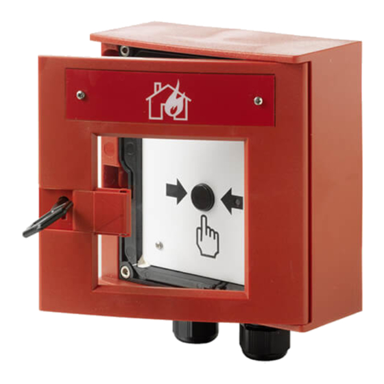
- Page 1 FDM243H Manual call point Technical Manual Smart Infrastructure A6V10374021_f_en_-- 2020-09-04...
- Page 2 All rights created by patent grant or registration of a utility model or design patent are reserved. Issued by: Siemens Switzerland Ltd. Smart Infrastructure Global Headquarters Theilerstrasse 1a CH-6300 Zug Tel. +41 58 724-2424 www.siemens.com/buildingtechnologies Edition: 2020-09-04 Document ID: A6V10374021_f_en_-- © Siemens Switzerland Ltd, 2013 2 | 38 A6V10374021_f_en_--...
-
Page 3: Table Of Contents
Table of contents About this document................. Applicable documents ................Technical terms ..................History of changes..................Safety ....................... Safety notes....................Safety regulations for the method of operation......... Standards and directives complied with ........... Release Notes ..................Structure and function ................Overview....................3.1.1 Details for ordering .............. - Page 4 Replacing the glass insert ................ Specification ..................... Technical data ..................Dimensions....................Master gauge for recesses ............... Environmental compatibility and disposal..........Index........................4 | 38 A6V10374021_f_en_--...
-
Page 5: About This Document
About this document 1 About this document Goal and purpose This document contains all information on the manual call point FDM243H. Following the instructions consistently will ensure that the product can be used safely and without any problems. Target groups... -
Page 6: Applicable Documents
FS720 Fire detection system - Commissioning, Maintenance, Troubleshooting A6V10211076 Operation Manual Fire control panel / Fire terminal FC72x / FT724 A6V10229261 List of compatibility (for 'Cerberus™ PRO' product line) A6V10356927 Data sheet Manual call point FDM243H A6V10374023 Installation Manual call point FDM243H 6 | 38 A6V10374021_f_en_--... -
Page 7: Technical Terms
About this document Technical terms 1.2 Technical terms Term Explanation FDnet/C-NET Addressed detector line Light-emitting diode 1.3 History of changes The reference document's version applies to all languages into which the reference document is translated. The first edition of a language version or a country variant may, for example, be version 'd' instead of 'a' if the reference document is already this version. -
Page 8: Safety
Safety Safety notes 2 Safety 2.1 Safety notes Comply with the following safety notes to protect life, limb, and property. The safety notes in the document include the following elements: ● Symbol for hazard ● Signal word ● Type and source of hazard ●... -
Page 9: Safety Regulations For The Method Of Operation
2.2 Safety regulations for the method of operation National standards, regulations and legislation Siemens products are developed and produced in compliance with the relevant European and international safety standards. Should additional national or local safety standards or legislation concerning the planning, mounting, installation,... - Page 10 Disregard of the safety regulations Before they are delivered, Siemens products are tested to ensure they function correctly when used properly. Siemens disclaims all liability for damage or injuries caused by the incorrect application of the instructions or the disregard of danger warnings contained in the documentation.
-
Page 11: Standards And Directives Complied With
Safety Standards and directives complied with 2.3 Standards and directives complied with A list of the standards and directives complied with is available from your Siemens contact. 2.4 Release Notes Limitations to the configuration or use of devices in a fire detection installation with a particular firmware version are possible. -
Page 12: Structure And Function
Indication of the condition (Alarm, localization or test) by means of a dichromatic LED ● Integrated line separation function ● Communication via FDnet/C-NET ● Sturdy housing for use outdoors and in humid areas Manual call point FDM243H 3.1.1 Details for ordering Manual call point FDM243H: Type Order no. Designation FDM243H S54311-F8-A1... -
Page 13: Product Version
20191 2PFS 1P S54310-F13-A1 Technical documentation see: www.siemens.com/bt/download Siemens Switzerland Ltd, CH-6300 Zug Country of Origin: Switzerland Figure 2: Example packaging label Depending on the product and various approvals, the product labels may differ in terms of the type of information provided and its layout. -
Page 14: Setup
Setup 3.2 Setup 3.2.1 Manual call point The manual call point FDM243H triggers an alarm when the glass insert is pushed in and the alarm button is pressed (indirect activation). The alarm is immediately transmitted to the control panel. When the alarm is activated, the switching unit must be reset and a new glass insert installed. -
Page 15: Connections
Structure and function Setup 3.2.2 Connections The manual call point has eight spring clips on the rear of the switching unit; these are for the detector line and for connecting external alarm indicators. Figure 4: Spring clips on the rear of the switching unit 3.2.3 Indication elements An LED is built into the switching unit as an internal alarm indicator. -
Page 16: Function
Structure and function Function 3.3 Function 3.3.1 Danger levels The manual call point can transmit the following danger levels to the control panel: Danger level Meaning Normal state, no danger Alarm Door status Danger level Meaning Door closed Door open The evaluation of the danger level and the resulting measures (e.g. activation of remote transmission) are configured on the control panel. -
Page 17: Diagnosis Levels
Structure and function Function Please observe the documentation for your fire control panel. Not every fire control panel allows test mode to be activated automatically. For some fire control panels, this function must be set explicitly. This setting may be automatically deactivated under certain circumstances. - Page 18 Structure and function Function Behavior of control panels that support degraded mode operation: ● Alarming is still ensured in degraded mode operation. However, in degraded mode only collective alarming is possible. This means that in the event of an alarm, it is possible to identify the FDnet/C-NET detector line but not the exact location of the detector triggering the alarm.
-
Page 19: Accessories
3.4 Accessories 3.4.1 Glass insert FDMG298 ● For alarm activation and protection against soiling ● Compatible with: – Manual call point FDM243H ● Order no.: S54311-B8-A1 3.4.2 Key FDMK294 ● Plastic key ● For opening doors on manual call points ●... -
Page 20: Planning
Planning Compatibility 4 Planning 4.1 Compatibility Compatible with control panels that support the FDnet/C-NET detector line. Detector line Control panel FC20xx FC72x SIGMASYS AlgoRex FDnet – – – C-NET – – – X = compatible – = not compatible You will find detailed information in the 'List of compatibility'. 4.2 Fields of application The manual call points are intended for use in places where a fire can be detected by people who can manually trigger an alarm. -
Page 21: Mounting/Installation
1. Preparation (see the chapter 'Preparation') 2. Installation (see the chapter 'Installation') 3. Electrical connection (see the chapter 'Installation') 5.1 Preparation For manual call point FDM243H, the surface-mounted cables are fed into the housing from below. Switching unit Keyhole cover... -
Page 22: Installation
2. Pull the cables through the entry opening(s) into the housing. 3. Tighten the cable gland so that it is properly sealed. a The manual call point is now prepared for electrical connection. Figure 6: Screw holes for manual call point FDM243H 22 | 38 A6V10374021_f_en_--... -
Page 23: Installation
Mounting/Installation Installation 5.3 Installation Notes on work on electrical installations CAUTION Electrical voltage on lines Risk of injury due to electric shock ● During mounting and installation work, electrical voltage must not be applied to the lines. WARNING Deactivating the manual call points prevents alarms from being forwarded. Alarming does not take place. - Page 24 LINE Ext. AI SHIELD Figure 8: Connection diagram for manual call point FDM243H Connecting the manual call point The manual call point has eight spring clips on the rear of the switching unit; these are for the detector line and for connecting external alarm indicators.
- Page 25 Mounting/Installation Installation 5. Connect the switching unit to the housing by tightening the four Allen head screws (2) firmly. – Check whether the button is protruding by about 3 mm. – If the alarm button is pressed in, reset it. See the 'Checking function [➙ 27]' chapter 6.
-
Page 26: Commissioning
Commissioning Localization and device testing 6 Commissioning The devices are commissioned via the control panel. The exact procedure is described in the control panel documentation. Conduct a performance check once commissioning is complete. 6.1 Localization and device testing The manual call points have an internal alarm indicator. This internal alarm indicator may also be activated from the control panel for localization and device testing. -
Page 27: Checking Function
6.2 Checking function Checking is usually performed from the fire control panel, but it may also be performed from the manual call point. Figure 11: Resetting manual call point FDM243H Stopping lever for resetting Checking from the fire control panel The manual call point is installed and electrically connected. - Page 28 Commissioning Checking function 8. Check whether an alarm is displayed on the fire control panel. 9. Set the detector line to 'Normal operation' on the fire control panel. a The detector line is ready for operation again. Checking from the manual call point You can activate test mode in the fire control panel by opening the door, and deactivate it by closing the door again.
- Page 29 Commissioning Checking function – NOTICE! If the alarm button is pressed when the LED is not flashing green, a genuine alarm will be activated. 5. If the LED is flashing green, press the alarm button immediately. The test alarm is transmitted. The LED also flashes red by way of confirmation.
-
Page 30: Maintenance / Repair
Maintenance / Repair Resetting after an alarm 7 Maintenance / Repair 7.1 Resetting after an alarm After an alarm is activated, the manual call point must be reset to a state in which it is ready for operation. Reset the detector to a state of operational readiness as follows: The glass insert has been shattered and the alarm button is pressed. -
Page 31: Status Query
Maintenance / Repair Status query 7.2 Status query Status query on the control panel Depending on the authorization level of the user and the control panel type, different actions can be performed from the control panel. Observe the notices in the control panel documentation. Document 009052 applies to fire control panels FC20xx. - Page 32 Maintenance / Repair Status query Figure 13: Installing the glass insert Door Glass insert Retainer Guides Resetting the alarm button The alarm button is pressed. The door is open. ◈ Place the key (1) onto the round guide and turn it clockwise so that the black stopping lever (2) is pushed downward.
- Page 33 Maintenance / Repair Status query Figure 14: Resetting the alarm button Stopping lever A6V10374021_f_en_-- 33 | 38...
-
Page 34: Specification
Specification Technical data 8 Specification You will find information on approvals, CE marking, and the relevant EU directives for this device (these devices) in the following document(s); see 'Applicable documents' chapter: ● A6V10356927 See also Applicable documents [➙ 6] 8.1 Technical data You will find information on approvals, CE marking, and the relevant EU directives for this device (these devices) in the following document(s);... -
Page 35: Dimensions
Specification Dimensions Length of line ● Max. 30 m with unshielded cables, or when the shielding is connected to the positive pole of the detector base ● Max. 5 m, if the shielding is connected to earth Connections Detector line and external alarm indicators: Spring clips Design Spring clips Cable cross section... -
Page 36: Master Gauge For Recesses
Specification Master gauge for recesses 8.3 Master gauge for recesses 8.4 Environmental compatibility and disposal This equipment is manufactured using materials and procedures which comply with current environmental protection standards as best as possible. More specifically, the following measures have been undertaken: ●... -
Page 37: Index
Index Index Alarm button Impact Resetting ............. 32 Chemicals ........... 20 Alarm indicator ........... 16, 26 Moisture ............ 20 Application area Temperature.......... 20 Internal alarm indicator....... 16, 26 Ambient conditions ........ 20 Approvals ............ 34 Line separator CE marking............ 34 Function ............ 16 Collective behavior List of compatibility ......... 6, 18, 20 Degraded mode operation ...... 18 Compatibility............. 20 Maintenance intervals ........ 31... - Page 38 Issued by Siemens Switzerland Ltd Smart Infrastructure Global Headquarters Theilerstrasse 1a CH-6300 Zug +41 58 724 2424 www.siemens.com/buildingtechnologies © Siemens Switzerland Ltd, 2013 Technical specifications and availability subject to change without notice. A6V10374021_f_en_--...
Need help?
Do you have a question about the FDM243H and is the answer not in the manual?
Questions and answers