Table of Contents
Advertisement
Quick Links
Advertisement
Table of Contents

Related Manuals for Newland NLS-EVK3030

Summary of Contents for Newland NLS-EVK3030
- Page 1 NLS-EVK3030 Software Development Board User Guide...
- Page 2 Revision History Version Description Date V1.0.0 Initial release. September 12, 2016 V1.0.1 Updated the pictures and relevant texts. October 12, 2017 V1.0.2 Added an example of cable installation (EM2096). February 8, 2018 V1.0.3 Updated relevant texts. February 27, 2018 V1.0.4 Updated Pinout of J1 and Pinout of J2 sections.
-
Page 3: Table Of Contents
Table of Contents Revision History ............................- 2 - About This Guide ............................1 Introduction ............................... 1 Chapter 1 Electrical Specifications ......................2 EVK3030 Schematic Diagram ........................2 EVK3030 Block Diagram ........................... 3 Parts Placement Layout ..........................4 Scan Engine Port Pinouts ......................... 6 Pinout of J1 ............................ -
Page 5: About This Guide
About This Guide Introduction This manual provides instructions on how to use NLS-EVK3030 software development board (hereinafter referred to as “EVK3030”). EVK3030 is an upgrade of EVK3000 V2 with an additional USB port via which users can enjoy the USB feature of the scan engine connected. For more details about scan engines... -
Page 6: Chapter 1 Electrical Specifications
Chapter 1 Electrical Specifications EVK3030 Schematic Diagram... -
Page 7: Evk3030 Block Diagram
EVK3030 Block Diagram 1. Place a scan engine on EVK3030. 2. Connect the scan engine to EVK3030 with a 12-pin FFC cable. 3. Connect EVK3030 to PC. -
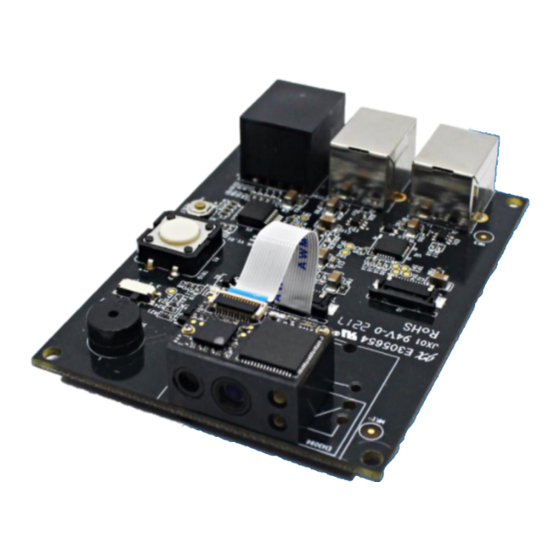
Page 8: Parts Placement Layout
Parts Placement Layout Buzzer Engine Trigger Reset... - Page 9 Part Description Note TTL-232 scan engine port Connect J3 or J5 to a host device. TTL-232/USB scan engine port Connect J3 or J4 or J5 to a host device. Connect J1 or J2 to a scan engine using TTL-232 signals. EVK3030 converts TTL-232 signals of RJ45 port scan engine into RS-232 signals.
-
Page 10: Scan Engine Port Pinouts
Scan Engine Port Pinouts... -
Page 11: Pinout Of J1
Pinout of J1 Signal Function BOOT It is connected to the DIP Switch. Put the switch on the right where EVK3030 is set as the low level. Under such circumstance, it will enter the Boot downloading mode. If it connects to the PIN of the scan engine which is NC, there will be no such function and DIP switch will be invalid. -
Page 12: Pinout Of J2
Pinout of J2 Signal Function Not connected. 3.3V power supply. Power-supply ground. RXD signal led out via the EVK3030 connects to the PIN (RXD) of the scan engine. TXD signal led out via the EVK3030 connects to the PIN (TXD) of the scan engine. -
Page 13: 12-Pin Ffc Cable Installation
12-pin FFC Cable Installation The example below shows how the EM2096 scan engine should be connected to the EVK3030. -
Page 15: Evk3030 Circuit Diagram
EVK3030 Circuit Diagram... -
Page 16: Operating Instructions
Operating Instructions Connecting EVK3030 to PC via J3 1. Connect J1 or J2 on EVK3030 to scan engine supporting TTL-232 port. 2. Connect J3 on EVK3030 to the serial port on PC with RS-232 cable (CBL037R). 3. Plug the power adapter (KSAS0120500150D5) into the power connector on the RS-232 cable. 4. - Page 17 Newland Auto-ID Tech. Co., Ltd. (Headquarter) Add: No.1, Rujiang West Rd., Mawei, Fuzhou, Fujian 350001, China Tel: +86 (0) 591 8397 9500 Fax: +86 (0) 591 8397 9216 E-mail: info@nlscan.com Web: www.newlandaidc.com Newland APAC Newland Taiwan Inc. Newland Korea Add: 7F-6, No. 268, Liancheng Rd., Jhonghe Dist. 235, New Taipei City, Taiwan Add: Biz.