Table of Contents
Advertisement
Advertisement
Table of Contents

Related Manuals for Newland NLS-EVK3030

Summary of Contents for Newland NLS-EVK3030
- Page 1 NLS-EVK3030 Software Development Board User Guide...
-
Page 2: Revision History
Revision History Version Description Date V1.0.0 Initial release. September 12, 2016 V1.0.1 Updated the pictures and relevant texts. October 12, 2017 Updated the pictures and relevant texts. Added an example of cable V1.0.2 February 28, 2018 installation (EM2096). -
Page 3: Table Of Contents
Table of Contents Revision History ............................- 2 - Introduction ............................... 1 Parts Placement Layout ..........................1 EVK3030 Block Diagram ..........................3 Scan Engine Port Pinouts ..........................4 Pinout of J1 ..............................4 Pinout of J2 ..............................5 12-pin FFC Cable Installation .......................... 5 EVK3030 Circuit Diagram .......................... -
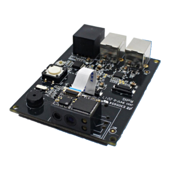
Page 4: Introduction
Introduction This manual provides instructions on how to use NLS-EVK3030 software development board (hereinafter referred to as “EVK3030”). EVK3030 is an upgrade of EVK3000V2 with an additional USB port via which users can enjoy the USB feature of the scan engine connected. For more details about scan engines which EVK3030 is applicable to, please ask the technical support for the scan engine supporting table. - Page 5 Part Description Note TTL-232 scan engine port Connect J3 or J5 to a host device. TTL-232/USB scan engine port Connect J3 or J4 or J5 to a host device. Connect J1 or J2 to a scan engine using TTL-232 signals. EVK3030 converts TTL-232 signals of RJ45 port scan engine into RS-232 signals.
-
Page 6: Evk3030 Block Diagram
EVK3030 Block Diagram RJ45 Port RS232 TTL to RS232 (J3) (SP3232) USB Port TTL to USB J1 (Hardware flow TTL232 (J5) CP2102) control) or J2 (No flow control) USB Port (J4) 1. Place a scan engine on EVK3030. 2. Connect the scan engine to EVK3030 with a 12-pin FFC cable. 3. -
Page 7: Scan Engine Port Pinouts
Scan Engine Port Pinouts Pinout of J1 Signal Function BOOT It is connected to the DIP Switch on the EVK3030. If the switch is put in the BOOT position (see the picture in the “Parts Placement Layout” section), where this pin is set at low level, then the engine connected enters the Boot downloading mode. -
Page 8: Pinout Of J2
Pinout of J2 Signal Function Not connected. 3.3V power supply. Power-supply ground. TTL level 232 receive data TTL level 232 transmit data. USB- USB D- differential data signal. USB+ USB D+ differential data signal. Not connected. Beeper output. Good Read LED output. nWake Reset signal input. - Page 9 The example below shows how the EM2096 scan engine should be connected to the EVK3030.
-
Page 10: Evk3030 Circuit Diagram
EVK3030 Circuit Diagram... -
Page 11: Operating Instructions
Operating Instructions Connecting EVK3030 to PC via J4 1. Connect J2 on EVK3030 to scan engine supporting USB port. 2. Connect J4 on EVK3030 to the USB port on PC with USB cable (FM300U). 3. When using USB HID-KBW, no driver is required; when using USB COM Port Emulation, install the corresponding driver (UFCOM driver) on PC. - Page 12 Newland Auto-ID Tech. Co., Ltd. (Headquarters) 3F, Building A, No.1, Rujiang West Rd., Mawei, Fuzhou, Fujian, China 350015 Tel: +86 - (0) 591-83978605 Fax: +86 - (0) 591-83979216 E-mail: contact@nlscan.com Web: www.newlandaidc.com Newland Europe BV Rolweg 25, 4104 AV Culemborg, The Netherlands...
Need help?
Do you have a question about the NLS-EVK3030 and is the answer not in the manual?
Questions and answers