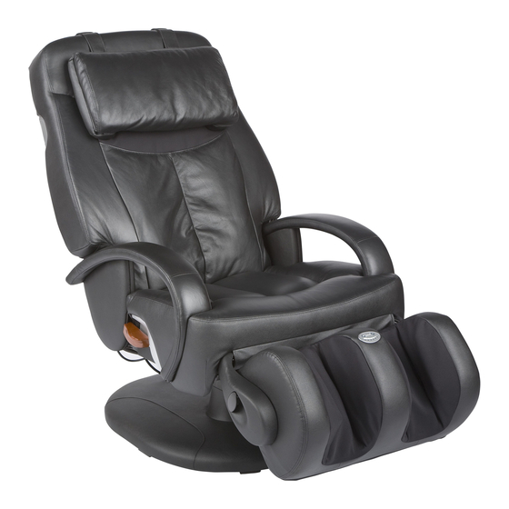
Human Touch HT-7120 Replacing Instructions
Replacing the foot and calf massager
Hide thumbs
Also See for HT-7120:
- Use & care manual (31 pages) ,
- Troubleshooting manual (10 pages) ,
- Quick start manual (4 pages)
Advertisement
To ensure that Human Touch
®
products are repaired in a manner that is fully consistent with the practices used during the manufacturing process, Human Touch requires that all
product repairs are performed using only factory-new parts and in accordance with these product repair instructions.
Tools Required:
Nail clipper or other instrument suitable for cutting zip ties, Phillips-head screwdriver, flat-head
screwdriver, vice grip, small hammer.
NOTE: SAVE ALL SCREWS FOR USE DURING REASSEMBLY.
REMOVING THE FOOT AND CALF MASSAGER
1. Lift the foot and calf massager up, then place a box or other sturdy object beneath it
for support.
2. Locate the air pump on the bottom of the chair, then remove the six sets of screws/washers
that secure the pump to the chair (Fig. 1).
3. Locate the connector box on the bottom left side of the chair, near the foot and calf
massager (Fig.2).
4. Using a Phillips-head screwdriver, remove the two screws that secure the connector box cover,
remove the cover, then disconnect the red connector.
5. Cut any zip ties that secure the cable that runs from the connector box to the foot and calf
massager, to free the cable from the chair base.
6. Remove the box or other sturdy object that is supporting the foot and calf massager,
allowing the massager to drop down to a vertical position.
7. Standing in front of the foot and calf massager, detach the upholstered flap that covers the
massager frame
(Fig.3).
NOTE: It is helpful to flip the upholstered flap up onto the seat cushion and place an object on
top of it to hold it out of the way.
(Fig.2)
REPLACING THE FOOT AND CALF MASSAGER
HT-7120
(Fig.1)
(Fig.3)
X1103
06/01/08
SERVICE LEVEL: 3
Screw/washer
Air pump
1
Advertisement
Table of Contents

Subscribe to Our Youtube Channel
Related Manuals for Human Touch HT-7120


Summary of Contents for Human Touch HT-7120
- Page 1 To ensure that Human Touch ® products are repaired in a manner that is fully consistent with the practices used during the manufacturing process, Human Touch requires that all SERVICE LEVEL: 3 product repairs are performed using only factory-new parts and in accordance with these product repair instructions.
- Page 2 Using a Phillips-head screwdriver, remove the two screws from the two brackets on the massager frame, then remove the brackets (Fig.4). Locate Pin A, insert a flat-head screwdriver between the pin head and the bracket, then tap the screwdriver handle to dislodge the pin from the bracket approximately 1/2 inch (Fig.4).
- Page 3 11. Reinstall the upholstered flap, by wrapping it around the massager frame and securing it using the hook and loop fasteners. Actuator bracket Pin A Pin B Bracket B Pin A Brackets Bracket A Bracket A Actuator bracket Please send any questions or comments regarding these instructions to: documentation@humantouch.com © 2008 Human Touch ® , LLC.
Need help?
Do you have a question about the HT-7120 and is the answer not in the manual?
Questions and answers