
Related Manuals for Dräger GMS-Gateway


Summary of Contents for Dräger GMS-Gateway
- Page 1 Alarm Monitoring System Count™ GMS-Gateway/ GMS-Gateway Volu Gebrauchsanweisung Montageanweisung Instructions for Use Installation Instructions...
-
Page 2: Table Of Contents
Node Object ......... 9 GMS-Gateway – Data Collectors Object ....12 GMS Gateway –... -
Page 3: Zu Ihrer Und Ihrer Patienten Sicherheit
Zu Ihrer und Ihrer Patienten Sicherheit For Your Safety and that of Your Patients Zu Ihrer und Ihrer Patienten For Your Safety and that of Your Sicherheit Patients Gebrauchsanweisung/Montageanweisung beachten Strictly follow the Instructions for Use/ Installation Instructions Jede Handhabung an der Anlage setzt die genaue Kenntnis und Beachtung dieser Gebrauchsanweisung/Montageanwei- Any use of the device requires full understanding and strict sung voraus. -
Page 4: Zweckbestimmung
Gebäude-Leittechnik). ment system). HINWEIS NOTE Das GMS-Gateway ist nicht zur Verwendung in The GMS gateway is not intended for use in the der Patientenumgebung bzw. in medizinisch patient environment or in rooms used for genutzten Räumen vorgesehen. Es ist nicht zur medical purposes. -
Page 5: Was Ist Was
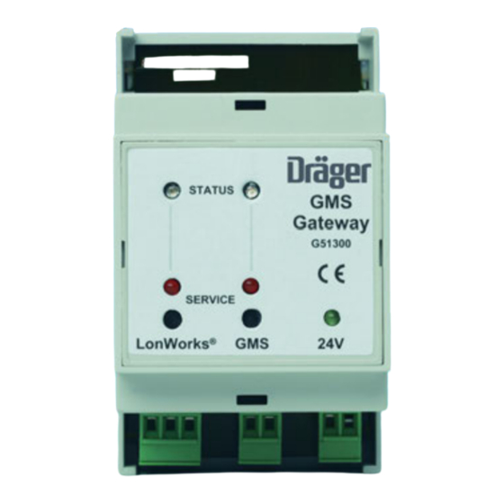
Was ist was What's What Was ist was What's What STATUS Gateway G51300 SERVICE LonWorks ® ® 1 Service LED, LonWorks side 1 Service-LED, LonWorks -Seite 2 Service LED, GMS side 2 Service-LED, GMS-Seite ® ® 3 Status DUO LED, LonWorks side 3 Status DUO-LED, LonWorks -Seite... -
Page 6: Montage
Montage Installation Montage Installation Das GMS-Gateway und das GMS-Gateway VoluCount™ sind The GMS gateway and the GMS gateway VoluCount™ are als Einbaugehäuse für Hutschienenmontage ausgeführt. Die constructed as housings for DIN rail installation. The unit is Montage erfolgt in einem Schalt-kasten oder einem separat installed in a switch box or in a separately available plastic erhältlichen Kunststoffgehäuse (G 50 748) durch:... -
Page 7: Abnahme Und Übergabe An Den Betreiber
Testing and Commissioning Abnahme und Übergabe an den Testing and Commissioning Betreiber Das GMS-Gateway und das GMS-Gateway VoluCount™ sind The GMS gateway and the GMS gateway VoluCount™ are Bestandteil des Dräger Alarm Monitoring Systems. components of the Dräger Alarm Monitoring System. -
Page 8: Lonworks ® -Interface
Interface ® ® GMS-Gateway GMS Gateway Das GMS-Gateway ist aus folgenden Objekten aufgebaut: The GMS gateway is constructed using the following objects: — Node Object (Objekt 0) — Node object (object 0) — Data Collectors Object (Objekt 1) — Data collectors object (object 1) —... -
Page 9: Node Object
® ® LonWorks -Interface LonWorks Interface Node Object Node Object Node Object Node Object Das Node Object dient zur Kontrolle aller Objekte im Knoten The node object serves to monitor all objects in the node bezüglich Selbsttests, Bereichsüberprüfungen, Fehlerkon- regarding self-tests, area inspections, error control, file trolle, File-Transfer etc. - Page 10 ® ® LonWorks -Interface LonWorks Interface Node Object Node Object Vorgeschriebene Netzwerkvariablen Prescribed Network Variables Mit nviRequest vom Format SNVT_obj_request ist die Anforde- A request for the status and checks of individual node objects rung von Stati und Kontrolle der einzelnen Knoten-Objekte is available through nviRequest in the format gegeben.
- Page 11 ® ® LonWorks -Interface LonWorks Interface Node Object Node Object Netzwerkvariablen im herstellerspezifischen Bereich Network Variables in the Manufacturer-specific Area Im herstellerspezifischen Bereich befindet sich die Ausgangs- The output variable nvoGmsState in the format SNVT_state is variable nvoGmsState vom Format SNVT_state. located in the manufacturer-specific area.
-
Page 12: Gms-Gateway - Data Collectors Object
® LonWorks -Interface LonWorks Interface GMS-Gateway – Data Collectors Object GMS Gateway – Data Collectors Object GMS-Gateway – Data Collectors Object GMS Gateway – Data Collectors Object Mit diesem Objekt werden die Daten von bis zu 8 GMS Daten- This object represents the data from up to 8 GMS data sammlern dargestellt. - Page 13 ® LonWorks -Interface LonWorks Interface GMS-Gateway – Data Collectors Object GMS Gateway – Data Collectors Object Configuration Properties des Data Collectors Objects Configuration Properties of the Data Collectors Object Für dieses Objekt existieren unterschiedliche Configuration There are different configuration properties for this object Properties, die für die Aussendung der Output-Variablen...
-
Page 14: Area Control Units Object
® ® LonWorks -Interface LonWorks Interface Area Control Units Object Area Control Units Object Area Control Units Object Area Control Units Object Für die Darstellung der Daten des Area Control Units Objects To represent the data for the area control units object, there stehen zwei Varianten zur Verfügung: are two versions available: —... - Page 15 ® ® LonWorks -Interface LonWorks Interface Area Control Units Object Area Control Units Object Netzwerkvariablen des Area Control Units Objects Network Variables for the Area Control Units Object Es existieren ausschließlich 50 Output-Variablen, welche als There are only 50 output variables, structured as an array. The Array ausgebildet sind.
- Page 16 ® ® LonWorks -Interface LonWorks Interface Area Control Units Object Area Control Units Object Area Control Units Object Variante 2 Area Control Units Object Version 2 (Alarm + Pressure, digitale und analoge (alarm and pressure, digital and analogue Darstellung) display) Mit diesem Objekt werden die digitalen Daten von bis zu 50 This object is used to display the digital data of up to 50 area Area Control Units dargestellt.
- Page 17 ® ® LonWorks -Interface LonWorks Interface Area Control Units Object Area Control Units Object Die Bits der vk5_state sind wie folgt definiert: The bits of vk5_state are defined as follows: Vk5_state[0] Wertigkeit/ Value Information Vk5_state[1] Wertigkeit/ Value Information Bit 7 2^7=128 Gas 1 Low Bit 7...
- Page 18 ® ® LonWorks -Interface LonWorks Interface Area Control Units Object Area Control Units Object — MinDeltaLevel für das Area Control Units Object — MinDeltaLevel for the Area Control Units Object Dieser Konfigurationsparameter vom SCPT-Typ 88 ermög- This configuration parameter of SCPT type 88 enables licht das Senden bei Veränderung eines Analogwertes nur transmission when an analogue value changes only after nach Abweichung um MinDeltaLevel in % vom aktuellen...
-
Page 19: Gms-Gateway Volucount™ - Volucount Object
® LonWorks -Interface LonWorks Interface GMS-Gateway VoluCount™ – Volucount Object GMS Gateway VoluCount™ – Volucount Object GMS-Gateway VoluCount™ – Volucount Object GMS Gateway VoluCount™ – Volucount Object Mit diesem Objekt werden die Daten von bis zu 25 Volucounts This object is used to represent the data of up to 25 dargestellt. - Page 20 ® ® LonWorks -Interface LonWorks Interface GMS-Gateway VoluCount™ – Volucount Object GMS Gateway VoluCount™ – Volucount Object Die Bits der nviResetStates sind wie folgt definiert: The bits of the nviResetStates are defined as follows: nviResetState Reset von nviResetState Reset von...
- Page 21 ® LonWorks -Interface LonWorks Interface GMS-Gateway VoluCount™ – Volucount Object GMS Gateway VoluCount™ – Volucount Object — MinDeltaLevel für das Volucount Object — MinDeltaLevel for the Volucount Object Dieses Konfigurationsparameter vom SCPT-Typ 88 ermög- This configuration parameter of SCPT type 88 enables licht das Senden bei Veränderung eines Analogwertes nur...
-
Page 22: Betrieb
Betrieb Operation Betrieb Operation Allgemeines General Das GMS-Gateway bzw. das The GMS gateway resp. the GMS GMS-Gateway VoluCount™ ist die gateway VoluCount™ is the data Datenschnittstelle zwischen dem Dräger interface between the Dräger Alarm ® ® Alarm System und einem LonWorks... -
Page 23: Status Duo-Led Der Gms-Seite
Betrieb Operation Status DUO-LED der GMS- Status DUO LED on the GMS Seite Side 1 Die Status DUO-LED signalisiert fol- 1 The status DUO LED signals the gende Betriebszustände: following operational states: — Grün statisch: Normaler Betriebszu- — Steady green: Normal operating STATUS stand. -
Page 24: Aufbereiten
Aufbereiten Purify Aufbereiten Purify GEFAHR DANGER Keine Desinfektion! Do not disinfect! Keine Reinigungsmittel benutzen, die Chlor oder Do not use cleaning agents which release Sauerstoff freisetzen! chlorine or oxygen! Keine Lösungsmittel wie Benzin oder Äther Do not use solvents such as benzine or benutzen! Dies kann die Oberfläche zerstören. -
Page 25: Fehler - Ursache - Abhilfe
Fehler – Ursache – Abhilfe Fault – Cause – Remedy Fehler – Ursache – Abhilfe Fehler Ursache Abhilfe Grüne Lampe 24 V DC leuchtet nicht. Spannungsversorgung unterbrochen. Spannungsversorgung durch Fachleute instandsetzen lassen. Status LED der GMS-Seite leuchtet Hardwaredefekt Durch Fachleute instandsetzen lassen. durchgängig rot oder gelb. -
Page 26: Technische Daten
01:00:00:01 GMS Gateway AP V2_00 02:00:00:00 (G 51 297) (G 51296) GMS Gateway AP V2_00 02:00:00:00 (G 51296) GMS-Gateway VoluCount™ GMS gateway VoluCount™ SW-Version GMS-Seite: VCG_0100 (G 41 893) 01:00:00:00 SW version on GMS side: ® VCG_0100 (G 41 893) -
Page 27: Stichwortverzeichnis
Stichwortverzeichnis Index Abnahme und Übergabe an den Betreiber ....7 Area Control Units Object ......14 Area Control Units Object . - Page 28 Richtlinie 93/42/EWG Directive 93/42/EEC über Medizinprodukte concerning Medical Devices 90 38 788 - GA 6918.000 de/en 90 38 788 - GA 6918.000 de/en © Dräger Medical GmbH © Dräger Medical GmbH Ausgabe/Edition: 4 – 2015-01 Edition: 4 – 2015-01 Subject to alteration Änderungen vorbehalten Ab 2015-08: As of 2015-08:...
Need help?
Do you have a question about the GMS-Gateway and is the answer not in the manual?
Questions and answers