Table of Contents
Advertisement
Quick Links
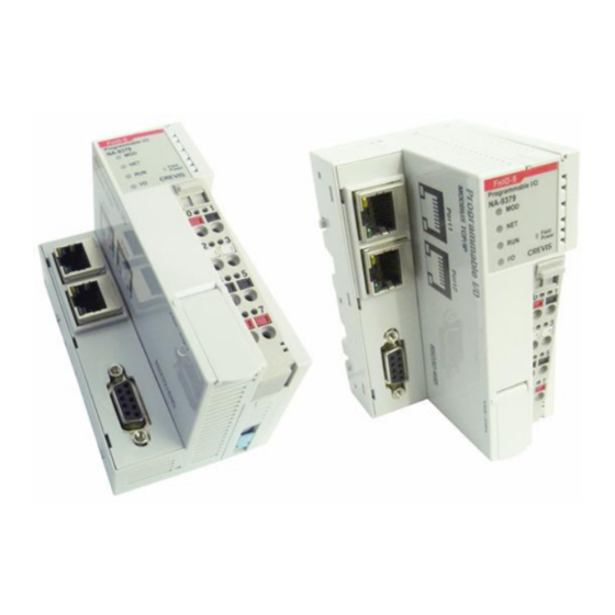
Programmable I/O (PIO) NA-9379, Basic setting
1 Function and area of use
The Programmable I/O (PIO) combines CODESYS control with the opportunity to build control sys-
tems to the exact size and specifications for the I/O signals involved.
In this document "PIO" are used for "Programmable I/O" (NA-9379).
2 About this Start Up document
Copyright © Beijer Electronics, 2014
This documentation (below referred to as 'the material') is the property of Beijer Electronics. The holder or
user has a non-exclusive right to use the material.
The holder is not allowed to distribute the material to anyone outside his/her organization except in cases
where the material is part of a system that is supplied by the holder to his/her customer.
The material may only be used with products or software supplied by Beijer Electronics.
Beijer Electronics assumes no responsibility for any defects in the material, or for any consequences that
might arise from the use of the material.
It is the responsibility of the holder to ensure that any systems, for whatever applications, which is based on
or includes the material (whether in its entirety or in parts), meets the expected properties or functional re-
quirements.
Beijer Electronics has no obligation to supply the holder with updated versions.
This Start Up document should not be considered as a complete manual. It is an aid to be
able to start up a normal application quickly and easily.
Use the following software and drivers in order to obtain a stable application:
Programming software
• CODESYS V3.5 SP3 Patch 1 or later , programming the PIO
• Compiler version 3.5.3.10 (CODESYS V3.5 SP3 Patch 1)
• IOGuidePro 1.1.0.8 #0004 or later
Device description, Crevis PIO NA-9379
• PIO_DeviceDescription 20140416.devdesc(.xml) or later, enable PIO in CODESYS
Library manager, CODESYS
• Standard 3.5.2.0 (System)
• IoStandard 3.5.3.0 (System)
• Time and Date 3.5.1.0
• Ethernet 3.4.2.0
• Modbus Master TCP 3.5.3.0 (IoDrvModbusTCP)
• Modbus Slave TCP 3.5.3.0 (IoDrvModbusTCPSlave)
Beijer Electronics Automation AB − a Beijer Electronics Group company
Head Office
Beijer Electronics Automation AB
P.O. Box 426, Stora Varvsgatan 13a
SE-201 24 Malmö, SWEDEN
Telephone +46 40 35 86 00
Fax +46 40 93 23 01
Reg no. 556701-3965 VAT no SE556701396501 www.beijer.se info@beijer.se
Subsidiaries
Norway, Drammen: Beijer Electronics AS, +47 32 24 30 00
Finland, Vantaa: Beijer Electronics Oy, +358 207 46 35 00
Denmark, Roskilde: Beijer Electronics A/S, +45 75 76 66
Estonia, Tallinn: Beijer Electronics Eesti Oü, +372 6 518140
Latvia, Riga: Beijer Electronics SIA, +371 6 7842280
Lithuania, Kaunas: Beijer Electronics UAB, +370 5 2323101
KI00341 2014-10
1 (35)
Advertisement
Table of Contents

Related Manuals for Beijer Electronics NA-9379


Summary of Contents for Beijer Electronics NA-9379
-
Page 1: Function And Area Of Use
2 About this Start Up document Copyright © Beijer Electronics, 2014 This documentation (below referred to as ‘the material’) is the property of Beijer Electronics. The holder or user has a non-exclusive right to use the material. The holder is not allowed to distribute the material to anyone outside his/her organization except in cases where the material is part of a system that is supplied by the holder to his/her customer. -
Page 2: First Step
Crevis FnIO S-Series All manuals • Start Up document “Programmable I/O (PIO) NA-9379, Communication”, KI00342 Start Up document “iX TxA/TxB - Programmable I/O (PIO) NA-9379”, KI00343 This document and other Start Up documents can be obtained from our homepage. Please use the address manual@beijer.se for feedback on our Start Up documents. -
Page 3: Table Of Contents
IP setting (default) ..............................7 Set the IP with BootP server ............................ 7 7 Configuration of CODESYS ............................9 Add PIO (NA-9379) to CODESYS ........................... 9 8 Configuration of PIO in CODESYS ..........................11 Programming and configuration ........................... 11 How to add a POU ..............................12 How to add a Task .............................. -
Page 4: Specification
Programmable I/O (PIO) NA-9379, Basic setting KI00341 2014-10 5 Specification 5.1 Interface, PIO (NA-9379) (1) 2 Ports RJ-45 for Ethernet PIO has a built-in 10/100Mbps Ethernet Port and switch hub (internally). Caution! Do not use two ports connected to the same hub. -
Page 5: Led Indicator
Programmable I/O (PIO) NA-9379, Basic setting KI00341 2014-10 5.2 LED Indicator LED Status when the module is operating normally • Green ON : MOD, RUN, IO • Yellow flashing and Green ON : LAN Port LED LED No. LED Function / Description... - Page 6 Programmable I/O (PIO) NA-9379, Basic setting KI00341 2014-10 5.2.4 I/O LED (Extension Module Status LED) Status LED is To indicate Not Powered Device has no expansion module or may not be powered No Expansion Module On-line, Flashing FnBus is normal but does not exchanging I/O data.
-
Page 7: Setup Ip Address In Pio
Programmable I/O (PIO) NA-9379, Basic setting KI00341 2014-10 6 Setup IP address in PIO The IP address can be set with Bootp or DHCP server. Default value are BootP. 6.1 IP setting (default) Default IP 192.168.100.100 Subnet 255.255.0.0 Gateway 192.168.0.1 Update F/W 192.168.100.10... - Page 8 Programmable I/O (PIO) NA-9379, Basic setting KI00341 2014-10 • The new IP-adress must be set within this time “one minute” - Click on “Add New Device” - Set IP address, Subnet Mask and gateway - Restart the PIO - When the MAC address is shown, click on ”OK”...
-
Page 9: Configuration Of Codesys
Programmable I/O (PIO) NA-9379, Basic setting KI00341 2014-10 7 Configuration of CODESYS This installation has to be done once for every computer. 7.1 Add PIO (NA-9379) to CODESYS • Change “Standard” to “Professional” • Install PIO and I/O modules (device description file) to CODESYS (Programmable IO_NA9379.devdesc.xml and ST-xxxx.devdesc.xml) - Page 10 Programmable I/O (PIO) NA-9379, Basic setting KI00341 2014-10 • The file is installed under “PLCs” and the I/O moduls under “Miscellaneous” 10 (35) www.beijer.se...
-
Page 11: Configuration Of Pio In Codesys
Programmable I/O (PIO) NA-9379, Basic setting KI00341 2014-10 Configuration of PIO in CODESYS 8.1 Programming and configuration • Start “CODESYS” • Click “File” and Choose “New project” • In “Templates”, mark “Standard project” • In “Name”, write the name of the project •... -
Page 12: How To Add A Pou
Programmable I/O (PIO) NA-9379, Basic setting KI00341 2014-10 8.2 How to add a POU • Highlight the “Application” option in the “Device” window and right click • Select “Add Object” and choose “POU”. Customize the POU according to desired characteristics. -
Page 13: How To Add A Task
Programmable I/O (PIO) NA-9379, Basic setting KI00341 2014-10 8.3 How to add a Task When a “Standard project” is selected, it automatically creates a "Main Task" • Highlight the “Application” option (to make a “Task Configuration”) or highlight the “TaskConfiguration” (to make a “Task”) •... -
Page 14: Plc Setting
Programmable I/O (PIO) NA-9379, Basic setting KI00341 2014-10 8.5 PLC setting • Interval time for the application (default value 20 ms) Update the I/O, set the Bus cycle task and Output handle at stop. • Double click at “Device (NA9379)” and select “PLC setting” and set like picture. -
Page 15: Select I/O Module
Programmable I/O (PIO) NA-9379, Basic setting KI00341 2014-10 8.6 Select I/O module • Highlight the “Slot (Slot)” option in the “Device” window and right click at the module place “Empty” • Click at “Plug Device”, mark the module and “double click” at module or “Plug Device”... -
Page 16: Setting Device Parameter And I/O Mapping
Programmable I/O (PIO) NA-9379, Basic setting KI00341 2014-10 8.7 Setting Device Parameter and I/O Mapping • Mark the module and “right click” and then “Edit Object” or “double click” at module 8.7.1 Parameter setting (I/O Module) • Mark the module and “right click” and then “Edit Object” or “double click” at module Setting value can be read in the manual “FnIO_Configuration_Parameter_Memory_Register”... -
Page 17: Program Example
Programmable I/O (PIO) NA-9379, Basic setting KI00341 2014-10 Program example The folder “ProgExample_PIO_Basic” contains the program example from this StartUp document. Can be downloaded from our homepage. 9.1 New project • Configure the project like 9.2 Add Global Variable and Persistent Variables The easiest way to edit the variables: use “textual”... - Page 18 Programmable I/O (PIO) NA-9379, Basic setting KI00341 2014-10 • Persistent Variables 18 (35) www.beijer.se...
-
Page 19: I/O Mapping
Programmable I/O (PIO) NA-9379, Basic setting KI00341 2014-10 9.3 I/O Mapping • Mapping the I/O Result • Do the same for all input, output (digital and analog) 19 (35) www.beijer.se... -
Page 20: Write Program In "Plc_Prg
Programmable I/O (PIO) NA-9379, Basic setting KI00341 2014-10 9.4 Write program in “PLC_PRG • Rebuild the program • If no Error, go to next step! View error, warning and message with “View \ Messages” NOTE! When “Generate code” there can be warning(s). It´s only a warning. The project is working correct. -
Page 21: Transfer Codesys Project To Pio
Programmable I/O (PIO) NA-9379, Basic setting KI00341 2014-10 9.5 Transfer CODESYS project to PIO A gateway needs to be created in order to communicate between the PC and the PIO • Double click the “Device(NA9379)” option under “Devices” • Select the “Communication setting” options •... - Page 22 Programmable I/O (PIO) NA-9379, Basic setting KI00341 2014-10 • Select the device that the project will be downloaded to and press “Set active path”. This device will be highlighted by a bold font. • Download the project to the device (TxB SoftControl) which was selected above menu “Online”...
-
Page 23: Monitor
Programmable I/O (PIO) NA-9379, Basic setting KI00341 2014-10 9.6 Monitor • I/O module • Global variable 23 (35) www.beijer.se... -
Page 24: Project Backup
Programmable I/O (PIO) NA-9379, Basic setting KI00341 2014-10 10 Project backup 10.1 CODESYS, Create backup files If this option is activated, at each saving the project will not only be saved in <projectname>.project but also copied to a file <projectname>.backup. -
Page 25: Persistent Variables (32 Kbyte)
Programmable I/O (PIO) NA-9379, Basic setting KI00341 2014-10 11 Persistent variables (32 kbyte) Persistent variables (battery powered, 6 days) can ONLY be declared in a special global variables list of object type, which is assigned to an application. There might be only ONE such list per application. -
Page 26: Appendix
Programmable I/O (PIO) NA-9379, Basic setting KI00341 2014-10 12 Appendix 12.1 Environment specification Environmental specification Operating Temperature -20 ~ +60°C Storage Temperature -40 ~ +85°C Relative Humidity 5 ~ 90% non-condensing Mounting DIN rail General specification (TBD) Shock Operating IEC 60068-2-6... -
Page 27: Interface Specification
Protocol Modbus TCP, DHCP, BOOTP, SNMP (ARP not supported) Max. Socket Max 18 connection. 6 UDP: Is used by CODESYS, BootP, NA-9379 (Network Variable), etc 12 TCP: Is used by Modbus TCP Master/Slave. - Example NA-9189/NA-9289 (Modbus TCP Slave). - Six of this connection are “TCP_LISTEN” used by HMI, etc... - Page 28 Programmable I/O (PIO) NA-9379, Basic setting KI00341 2014-10 General specification System Power Supply voltage: 24Vdc nominal Supply voltage range: 11 ~ 28.8 Vdc Protection: Output current limit (Min. 1.5A) Reverse polarity protection Power Dissipation 110 mA typical @ 24Vdc Current for I/O Module 1.5A @ 5Vdc...
-
Page 29: Wiring Diagram, Pio
Programmable I/O (PIO) NA-9379, Basic setting KI00341 2014-10 12.3 Wiring diagram, PIO 12.3.1 PIO NA-9379, RTB terminal block Signal Description Signal Description System Power 0V System Power 0V FG (Frame Ground) Field Power 0V Field Power 0V Field Power 24V Field Power 24V •... - Page 30 Programmable I/O (PIO) NA-9379, Basic setting KI00341 2014-10 12.3.3 RJ-45 Socket RJ-45 Signal Name Description TD + Transmit + TD - Transmit - RD + Receive + RD - Receive - Case Shield 12.3.4 RS232/485 Port for MODBUS/RTU Slave, Operator Panel or IOGuidePro...
-
Page 31: Dimension
Programmable I/O (PIO) NA-9379, Basic setting KI00341 2014-10 12.4 Dimension Unit: mm 12.5 Expansion The number of module that can be connected is 32. So the maximum length is 426 mm. Exception, ST-2748 is excepted to calculate maximum length because that is double width module. -
Page 32: Removable Terminal Block (Rtb)
Programmable I/O (PIO) NA-9379, Basic setting KI00341 2014-10 12.7 Removable Terminal Block (RTB) 12.8 Method of Wiring Connecting or removing the cable by pushing the terminal button for the relevant points. NOTE! The use of an incorrect supply voltage or frequency can cause severe damage to the component. -
Page 33: Check Compiler, Pio And Library Version
Programmable I/O (PIO) NA-9379, Basic setting KI00341 2014-10 12.11 Check Compiler, PIO and Library version • Check ”Compiler” Version • Check ”NA9379” (PIO) version Check ”Library” version • 33 (35) www.beijer.se... -
Page 34: Trouble Shooting
Programmable I/O (PIO) NA-9379, Basic setting KI00341 2014-10 12.12 Trouble Shooting 12.12.1 How to diagnose by LED indicator LED Status Cause Action All LED turns off No power Check main power Cable System power is not supplied Contact Sales team and send module for repair... - Page 35 Programmable I/O (PIO) NA-9379, Basic setting KI00341 2014-10 12.12.2 How to diagnose when device couldn’t communicate network Inspection of wrong or omission cable connection - Check status of cable connection for each node - Check that all color matches between connector and cable...
Need help?
Do you have a question about the NA-9379 and is the answer not in the manual?
Questions and answers