
Related Manuals for Beijer Electronics GT-5642


Summary of Contents for Beijer Electronics GT-5642
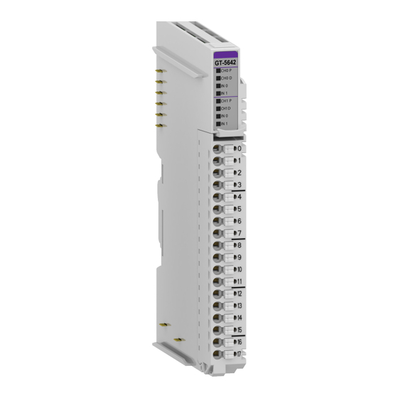
- Page 1 User Manual GT-5642 Pulse Output Module 2 ch, 24 VDC, 0.5 A, source, cage clamp, 18 pt removable terminal Doc ID: 151399 2025-02-20...
- Page 2 The information in this document is subject to change without notice and is provided as available at the time of printing. Beijer Electronics AB reserves the right to change any information without updating this publication. Beijer Electronics AB assumes no responsibility for any errors that may appear in this document.
-
Page 3: Table Of Contents
11. Hardware Setup ..................19 11.1. Space Requirements ................19 11.2. Mount Module to DIN Rail ..............20 11.3. Mount Removable Terminal Block ............22 11.4. Connect Cables to Removable Terminal Block ..........23 Beijer Electronics, Doc ID: 151399 2025-02... -
Page 5: About This Manual
About This Manual 1. About This Manual This manual contains information on the software and hardware features of the Beijer Electronics GT-5642 Pulse Output Module. It provides in-depth specifications, guidance on installation, setup, and usage of the product. 1.1. Symbols Used in This Manual This publication includes Warning, Caution, Note and Important icons where appropriate, to point out safety-related, or other important information. -
Page 6: Safety
Before using this product, please read this manual and other relevant manuals carefully. Pay full attention to safety instructions! In no event will Beijer Electronics be responsible or liable for damages resulting from the use of this product. The images, examples and diagrams in this manual are included for illustrative purposes. Because of the many variables and requirements associated with any particular installation, Beijer Electronics cannot take responsibility or liability for actual use based on the examples and diagrams. -
Page 7: About The G-Series System
IP, EtherCAT, PROFINET, CC-Link IE Field, PROFIBUS, CANopen, DeviceNet, CC-Link, MODBUS/Serial etc. • Expansion Module - Expansion module types: Digital IO, Analog IO, and Special modules. • Messaging - The system uses two types of messaging: Service messaging and IO messaging. Beijer Electronics, Doc ID: 151399 2025-02... -
Page 8: Io Process Data Mapping
Valid parameter data depends on the modules in use. For example, analog modules have settings of either 0-20 mA or 4-20 mA, and temperature modules have settings such as PT100, PT200, and PT500. The documentation for each module provides a description of the parameter data. 2025-02 Beijer Electronics, Doc ID: 151399... -
Page 9: Specifications
Voltage range: 15-30 VDC Power dissipation: Max. 45 mA @ 24 VDC except load Single wire IO cable max. 0.75 mm² (AWG18) Weight 63 g Module size 12 mm x 109 mm x 70 mm Beijer Electronics, Doc ID: 151399 2025-02... -
Page 10: Pulse Output Specifications
Max. +1 - +2147483647: Pulse direction output OFF. Max. -1 - -2147483647: Pulse direction output ON. Pulse output counter Signed 32 bit-wide Function Trapezoidal acceleration Protection Short protection Common type 4 common, field power 0V is common 2025-02 Beijer Electronics, Doc ID: 151399... -
Page 11: Digital Input Specifications
15 - 32 VDC Off-state voltage 8.3 VDC @ 25℃ On-stat current 3.10mA @ 30 VDC Input signal delay OFF to ON: Max. 0.3 ms ON to OFF: Max. 0.3 ms Nominal input impedance 10.72 kΩ typicals Beijer Electronics, Doc ID: 151399 2025-02... -
Page 12: Wiring Diagram
Field Power 0 V, common Direction output channel #1 Field Power 0 V, common Emergency stop input channel #1 Field Power 0 V, common Digital input channel #1 Field Power 0 V, common Shield Shield 2025-02 Beijer Electronics, Doc ID: 151399... -
Page 13: Led Indicator
Pulse output channel #1 Green Direction output channel #1 Green Emergency stop input channel #1 Green Digital input channel #1 Green LED channel status Status LED is Indication No signal Normal operation On signal Green Normal operation Beijer Electronics, Doc ID: 151399 2025-02... -
Page 14: Mapping Data From The Image Table
Byte RUN1 * ECP1 ACC1 CLR1 Multiple **** * RUNx: Pulse output run. ** ECPx (Enable Continuous Pulse): If this bit is “1” and Pulse output qty. is not 0, pulse output always runs. 2025-02 Beijer Electronics, Doc ID: 151399... - Page 15 1 (B’01) x10 Frequency multiple 2 (B’10) x100 Frequency multiple 3 (B’11) x1000 Frequency multiple Example: If Pulse frequency = 123, and Frequency multiple = 2, Real pulse output is 12.3 kHz (123 * 100). Beijer Electronics, Doc ID: 151399 2025-02...
-
Page 16: Parameter Data
Acceleration time ch#0 H Byte 2 Acceleration time ch#1 L Byte 3 Acceleration time ch#1 H The unit is ms if 1.000, then Acceleration time 1.000 ms. The maximum is 10.000 (10.000 ms = 10 s). 2025-02 Beijer Electronics, Doc ID: 151399... -
Page 17: Parameter Data
Parameter Data 9. Parameter Data Valid parameter length: 2 Bytes Bit no. Bit 7 Bit 6 Bit 5 Bit 4 Bit 3 Bit 2 Bit 1 Bit 0 Byte 0 Reserved Byte 1 Reserved Beijer Electronics, Doc ID: 151399 2025-02... -
Page 18: Example Of Acceleration Function
0xE8 Byte1 (H) 0x03 => Frequency = 25000 / Pulse count = 50000 / Acceleration time = 1.000 ms NOTE If the counter value is not sufficient, the maximum velocity may not be reached. 2025-02 Beijer Electronics, Doc ID: 151399... -
Page 19: Hardware Setup
Installation position is valid vertical and horizontal. The drawings are illustrative and may be out of proportion. CAUTION NOT following the space requirements may result in damaging the product. Beijer Electronics, Doc ID: 151399 2025-02... -
Page 20: Mount Module To Din Rail
• GT-5XXX • GT-7XXX GN-9XXX modules have three locking levers, one at the bottom and two on the side. For mounting instructions, refer to Mount GN-9XXX Module. Mount to DIN rail Dismount from DIN rail 2025-02 Beijer Electronics, Doc ID: 151399... - Page 21 11.2.2. Mount GN-9XXX Module To mount or dismount a network adapter or programmable IO module with the product name GN-9XXX, for example GN-9251 or GN-9371, see the following instructions: Mount to DIN rail Dismount from DIN rail Beijer Electronics, Doc ID: 151399 2025-02...
-
Page 22: Mount Removable Terminal Block
Hardware Setup 11.3. Mount Removable Terminal Block To mount or dismount a removable terminal block (RTB), see the instructions below. Mount a removable terminal block Dismount a removable terminal block 2025-02 Beijer Electronics, Doc ID: 151399... -
Page 23: Connect Cables To Removable Terminal Block
To connect/disconnect cables to/from the removable terminal block (RTB), see the instructions below. WARNING Always use the recommended supply voltage and frequency to prevent damage to the equipment and ensure optimal performance. Connect cable Disconnect cable Beijer Electronics, Doc ID: 151399 2025-02...
Need help?
Do you have a question about the GT-5642 and is the answer not in the manual?
Questions and answers