Advertisement
Quick Links
860452168
Issue 7, April 2014
www.commscope.com
SYSTIMAX 360
General
™
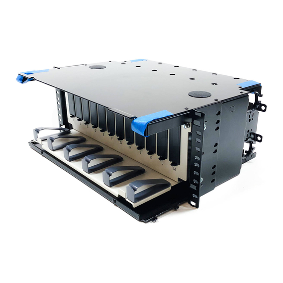
The SYSTIMAX 360
360G2 4U sliding, front access fiber optic combination shelf mounts onto a standard
19-inch (483mm), 23-inch (584mm) or ETSI equipment rack. This product is intended for indoor use or may be
used outdoors in a suitable protective enclosure.
Ordering information is listed below:
Material ID
760193896
360G2-4U-MOD-SD
760101089
360G2-4U IP-SD
SYSTIMAX 360
This product is covered by one or more of the following U.S. patents or their foreign equivalents:
7,113,667 B2, 7,200,314 B2
™
360G2 4U Sliding Front Access
Combination Shelf Instructions
Part No.
360G2 4U sliding modular cassette shelf
360G2 4U sliding adapter panel shelf
™
360G2 4U Sliding, Front Access Fiber Optic Combination Shelf
© 2014 CommScope, Inc. All rights reserved
Description
Page 1 of 21
Advertisement

Related Manuals for CommScope SYSTIMAX 360 360G2 4U Series

Summary of Contents for CommScope SYSTIMAX 360 360G2 4U Series
- Page 1 360G2 4U Sliding, Front Access Fiber Optic Combination Shelf This product is covered by one or more of the following U.S. patents or their foreign equivalents: 7,113,667 B2, 7,200,314 B2 © 2014 CommScope, Inc. All rights reserved Page 1 of 21...
-
Page 2: Tools Required
™ PartnerPRO Network Partner. Within the United States, report any missing/damaged parts or any other issues to CommScope Customer Claims at 1-866-539-2795 or email to claims@commscope.com. Outside the United States, contact your local account representative or PartnerPRO Network Partner. Tools Required •... - Page 3 860452168 Instruction Sheet Material ID Product No. Description 760122895 BAF-1/2-NPT Bracket for armor fitting, 1/2 NPT 760122903 BAF-3/4-NPT Bracket for armor fitting, 3/4 NPT 760122911 BAF-1-NPT Bracket for armor fitting, 1 NPT 760122929 BAF-1-1/4-NPT Bracket for armor fitting, 1-1/4 NPT...
- Page 4 860452168 www.commscope.com Instruction Sheet Step 1 – Verify Parts and Install Labels 1. Verify parts shipped with this unit against the parts listed in the table below. 2. Apply shelf ID labels to bulkhead, located approximately as shown, one on each side of panel (outside and inside).
- Page 5 860452168 Instruction Sheet Step 2 – Configure Mounting Brackets and Mount Shelf to Equipment Rack Configuration for 19” Rack Configuration for 23” Rack Configuration for ETSI Rack For ETSI configuration only, Front use these holes to secure mounting bracket on right side Side View 1.
- Page 6 860452168 www.commscope.com Instruction Sheet Step 3 – Install Building Cables/Outside Plant Cables (OSP) Note: All fiber installation shall be done with the internal mechanism pulled out from the outer shelf enclosure and fully lowered, as shown in the following illustrations.
- Page 7 860452168 Instruction Sheet 3. Locate cable-tie anchoring positions provided in upper sidewalls of shelf. 4. Route buffered building cables or PVC protected OSP fibers into shelf through oblong openings provided in upper rear corner of sidewalls. Use of protective spiral wrap around these fibers is highly recommended.
- Page 8 860452168 www.commscope.com Instruction Sheet Step 3B – Rear/Top Cable Entry Configuration Lower cable entry Bldg of OSP cable Splice organizer mounting panel Fiber slack storage (spool counter-clockwise) 12A1 clamp Spiral wrap (for protection) Fiber slack storage (spool clockwise) 1. Prepare fiber optic building cables or outside plant (OSP) cables. See 636299110-5 for cable preparation procedures for OSP cables.
- Page 9 860452168 Instruction Sheet Step 4 – Install Termination Devices Note: Modular cassettes, bezels, and adapter panels are normally ordered separately from the shelf. Some customer specific versions of this shelf come pre-terminated and will not require these steps. Step 4A – G2 Modular Cassette Application 1.
- Page 10 860452168 www.commscope.com Instruction Sheet Step 4B – G2 Bezel Application Splice tray Splice wallet Spool clockwise through fiber rings Bulkhead Spool clockwise through fiber rings G2 Bezel G2 Bezel (location A) (location G) 1. Starting at location A (the left-most position), plug a bezel into the bulkhead cutout until it snaps into place, as shown in figure above.
- Page 11 860452168 Instruction Sheet Step 4C – Adapter Panel Application 1. Starting at location A (the left-most position), plug an adapter panel into the bulkhead cutout, as shown in figure above. 2. Terminate a fiber pigtail into adapter panel, color keying as required. Repeat for all remaining locations.
- Page 12 860452168 www.commscope.com Instruction Sheet Step 4D – InstaPATCH Plus Module Application Note: InstaPATCH or ReadyPATCH cables use SYSTIMAX shelf mounted bracket (SMB) kit or rack mounted bracket (RMB) kit per instructions provided in 860448471 and 860380781 respectively. 1. Starting at location A (the left-most position), plug module into bulkhead cutout, as shown in figure above.
- Page 13 860452168 Instruction Sheet Step 4E – 360 InstaPATCH Plus Module Application Note: InstaPATCH or ReadyPATCH cables use SYSTIMAX shelf mounted bracket (SMB) kit or rack mounted bracket (RMB) kit per instructions provided in 860448471 and 860380781 respectively. 1. Starting at location A (the left-most position), plug module into bulkhead cutout, as shown in figure above.
- Page 14 860452168 www.commscope.com Instruction Sheet Step 5 – Splicing Provisions Note: Splice organizer trays and splice carriers are normally ordered separately from the shelf. Some customer specific versions of this shelf come pre-populated with these items and will not require these steps. Splicing operations are not covered in this document.
- Page 15 860452168 Instruction Sheet RoloSplice 1. Assemble components for mounting in the illustrated position, if required. See figure above. 2. Install plastic fasteners into splice organizer mounting panel as shown. 3. Assemble base of RoloSplice onto plastic fasteners and push in plungers to fasten.
- Page 16 860452168 www.commscope.com Instruction Sheet Adapter panel Splice tray Buffer tube .25” (6mm) OSP or indoor/outdoor cable Cable ties Notes: • It is recommended that splicing operations be performed on a work surface outside the shelf, prior to tray installation. Approximately 5 feet (1.5 meters) of buffer tube length should be prepared with an additional 3 feet (1 meter) of fiber exposed for splicing.
- Page 17 860452168 Instruction Sheet Plastic snap rivets Bundle buffer tubes on interior of shelf 3 trays stacked Fiber Management When Using Stackable Splice Trays 1. Trim all pigtail lengths to 3 feet (1 meter) or less. 2. Perform fusion splicing operations per best practices and snap splice sleeves into holders provided inside of tray.
- Page 18 860452168 www.commscope.com Instruction Sheet Step 7 – Install Front Loose Parts 1. Install left hardware bezel cover by inserting two tabs on shelf into openings on bottom of bezel cover. 2. Push bezel cover towards mounting rail until bezel overrides lock on shelf and snaps into place.
- Page 19 860452168 Instruction Sheet Step 8 – Install or Remove Front Door 1. To install front door, position door at 45° and align door clasps on lower corners of door to hinges on panel and push in on each corner to engage the two parts.
- Page 20 860452168 www.commscope.com Instruction Sheet Step 9 – Install Rear Loose Parts 1. To install rear door, align door clasps on lower corners of door to hinges on panel and push in on each corner to engage the two parts. 2. Swing door up and down freely to verify proper installation.
- Page 21 860452168 Instruction Sheet Step 10 – Install Fiber Designation Label Label holder Trough door Label hanger (3 places) 1. To print a designation label, go to http://www.commscope.com/Resources/Labeling-Templates and scroll down to 360G2 Panels and Shelves and select the appropriate label template.
Need help?
Do you have a question about the SYSTIMAX 360 360G2 4U Series and is the answer not in the manual?
Questions and answers