Table of Contents
Advertisement
Quick Links
WARNING: For Outdoor Use Only. Installation and service must be performed by a
qualified installer, service agency or the gas supplier.
WARNING: If the information in this manual is not followed exactly, a fire or explosion
may result causing property damage, personal injury, or loss of life.
WARNING: Do not store or use gasoline, or other flammable vapors and liquids, in the
vicinity of this or any other appliance.
An LP-cylinder not connected for use shall not be stored in the vicinity of this or any other
appliance.
DANGER: FIRE OR EXPLOSION HAZARD
If you smell gas:
Shut off gas to the appliance.
Extinguish any open flame.
If odor continues, leave the area immediately.
After leaving the area, call your gas supplier or fire department.
Failure to follow these instructions could result in fire or explosion, which could cause
property damage, personal injury, or death.
INSTALLER: Leave this manual with the appliance.
CONSUMER: Retain this manual for future reference.
Copyright 2020, T.I.
$10.00
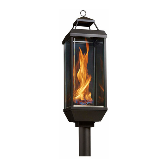
Tempest Lantern 24V
Natural Gas (sku 94900747) - Propane (sku 94900757)
Tested and
listed by
ANSI Z21.97-2017 /CSA 2.41-2017, CSA 2.17-2017
Outdoor Decorative Gas Appliances
Report # 0028GM083S
Hot glass will
cause burns.
Do not touch
glass until
cooled.
Never allow
childern to
touch glass.
Owner's Manual
Portland
OR
CARBON MONOXIDE
HAZARD
This appliance can produce
carbon monoxide which has
no odor.
Using it in an enclosed
space can kill you.
Never use this appliance in
an enclosed space such as a
camper, tent, car or home.
Part # 100-01534
Advertisement
Table of Contents

Related Manuals for Travis Industries Tempest


Summary of Contents for Travis Industries Tempest
- Page 1 Tempest Lantern 24V Owner’s Manual Natural Gas (sku 94900747) - Propane (sku 94900757) Tested and Portland listed by ANSI Z21.97-2017 /CSA 2.41-2017, CSA 2.17-2017 Outdoor Decorative Gas Appliances Report # 0028GM083S WARNING: For Outdoor Use Only. Installation and service must be performed by a qualified installer, service agency or the gas supplier.
-
Page 2: Overview
A copy is shown to the right. Important Registration and Service Information No other Tempest Lantern has the same serial number as yours. The serial number is on the safety label attached by a chain near the control panel. This serial number will be needed in case you require service of any type. -
Page 3: Table Of Contents
Wire Configuration - Direct-Run vs Troubleshooting Table ......24 Daisy-Chain Installations ....10 Warranty ..........25 Lantern Wiring Diagram ......11 Index ............26 © Travis Industries, Inc. 5/21/20 - 1534 Tempest Lantern 24v... - Page 4 Always follow the instructions in this manual. • Travis Industries, Inc. grants no warranty, implied or stated, for the installation or maintenance of your Lantern, and assumes no responsibility of any consequential damage(s).
-
Page 5: Features
Base Cover 2-1/2" (64mm) 4" 1-1/4" (102mm) (34mm) Mounting Bracket Control Assembly with Valve NOTE: Side clearances are measured from the glass – Top clearances are measured from the glass frame. © Travis Industries, Inc. 5/21/20 - 1534 Tempest Lantern 24v... -
Page 6: Installation Warnings
(not supplied). Notify your insurance company before hooking up this appliance. All relevant information on the Tempest Lantern is located on page 2, Important Information. You provide them page 2. The requirements listed below are divided into sections. All requirements must be met simultaneously. -
Page 7: Recommended Order Of Installation
Leak test the gas lines. Verify the Lantern works correctly and there are no gas leaks. Attach the control covers. 8. Give the manual to the home owner and explain the operation of the Lantern. © Travis Industries, Inc. 5/21/20 - 1534 Tempest Lantern 24v... -
Page 8: Placement Requirements
Keep combustibles away from the shaded heat zone of the Lantern (see illustration below). 26" (660mm) 8" (203mm) 8" (203mm) Measured from Glass Surface 2-1/2" (64mm) © Travis Industries, Inc. 5/21/20 - 1534 Tempest Lantern 24v... -
Page 9: Gas Line Requirements
A manual shutoff valve is required on the gas supply to the Lantern. It should be placed upstream of the control module. A shut-off valve is included with the Lantern. © Travis Industries, Inc. 5/21/20 - 1534 Tempest Lantern 24v... -
Page 10: Electrical Connection Requirements
This Lantern must be used with a 24VAC switched circuit. The transformer is sold separately. Travis Industries offers the following two transformers: -- 94800829 Powers 1 to 4 Lanterns (120v and 240v inputs). See the instruction sheet included with the transformer for details. -
Page 11: Lantern Wiring Diagram
The thermopile must connect to the control module as shown above (white/orange wire connects to the white thermopile wire and orange wire connects to red thermopile wire). Do not reverse the wires. If the wires are reversed, the Lantern will not work correctly. © Travis Industries, Inc. 5/21/20 - 1534 Tempest Lantern 24v... -
Page 12: Wiring Multiple Transformers To One Switch
A T T E N T I O N Hot (Black) Common (White) Ground (Green) WA R N I N G A T T E N T I O N © Travis Industries, Inc. 5/21/20 - 1534 Tempest Lantern 24v... -
Page 13: Wiring Multiple Lanterns To One Transformer
Daisy-Chain Example Hot (Black) Common (White) Ground (Green) Direct-Run Example WA R N I N G A T T E N T I O N Hot (Black) Common (White) Ground (Green) © Travis Industries, Inc. 5/21/20 - 1534 Tempest Lantern 24v... -
Page 14: Daisy-Chain Wire Length Chart
Wire 104' 14 G 242' 157' 113' 160' 12 G 369' 238' 173' 134' 108' 245' 144' 10 G 566' 366' 266' 206' 165' * Not available on some transformers. © Travis Industries, Inc. 5/21/20 - 1534 Tempest Lantern 24v... -
Page 15: Direct-Run Wire Length Chart
The wire will also be printed with a gauge number (e.g. AWG#14 = 14 gauge, 10AWG = 10 gauge, etc.). Do not use wires of dissimilar gauges (do not use 14 gauge & 10 gauge wire on the same transformer). © Travis Industries, Inc. 5/21/20 - 1534 Tempest Lantern 24v... -
Page 16: Polarity
CONNECT TO YELLOW WIRES, ALL 24V AC 24V AC WRONG! WHITE/YELLOW WIRES CONNECT TO Transformer Transformer DO NOT ALLOW A YELLOW WIRE TO WHITE/YELLOW WIRES. CONNECT TO A WHITE/YELLOW WIRE © Travis Industries, Inc. 5/21/20 - 1534 Tempest Lantern 24v... -
Page 17: Post Mount And Control Cover Installation
20 screws. (d) Attach the control cover to the Lantern with the two thumb screws. ! The safety label slides into place between the control cover and the Lantern body. © Travis Industries, Inc. 5/21/20 - 1534 Tempest Lantern 24v... -
Page 18: Lantern Assembly
(e.g. paper towel). (c) Place the rain cap on the top of the Lantern glass assembly. The cap will friction fit to assembly. © Travis Industries, Inc. 5/21/20 - 1534 Tempest Lantern 24v... -
Page 19: Post Or Pier Mounted Lantern
Post or Pier Mounted Lantern (Optional The tempest Lantern may be mounted to a 3” diameter post using the included post mount. This post may be surface mounted on a deck or similar platform with the optional post base kit. If the post is placed in a remote location, it may be sunk into the ground using concrete or other suitable means. -
Page 20: Wall Mounted Lantern (Optional)
Wall Mounted Lantern (Optional) The tempest Lantern may be mounted to an external wall an optional wall mount kit. Make sure that all clearances are can be maintained in your application. See the wall mount kit for assembly and installation instructions. -
Page 21: Before You Begin
Inspect the Lantern, burner, and supply lines for any damage prior to operation. The burner must be replaced prior to the appliance being put into operation if it is evident that the burner is damaged. Use only Travis Industries replacement burners. It may be difficult to see the burner operating in direct sunlight. -
Page 22: Maintaining Your Lantern
If it breaks it will shatter into small square pieces similar to a car windshield. It is special glass and if you break one or need to replace a piece use only 3/16” thick tempered glass supplied by your Tempest Lantern dealer. -
Page 23: Replacement Parts
Burner Assembly - NG 250-05516 Flame Spreader NG 250-01790 Burner Assembly - LP 250-05515 Flame Spreader LP 250-01791 Replacement parts can be obtained from your Tempest Lantern retailer (see www.tempesttorch.com). © Travis Industries, Inc. 5/21/20 - 1534 Tempest Lantern 24v... -
Page 24: Troubleshooting Table
THIS IS NORMAL Lantern makes Clicking Glass is moving inside the glass frame and the stainless steel parts Sounds are expanding and contracting with heat © Travis Industries, Inc. 5/21/20 - 1534 Tempest Lantern 24v... -
Page 25: Warranty
2. Travis Industries has the option of either repairing or replacing the defective component. 3. If your dealer is unable to repair your appliance's defect during the warranty period, they will process a warranty claim through TRAVIS INDUSTRIES, INC. The dealer will require you to supply a copy of your receipt showing the date of the appliance's purchase and the serial number on your appliance. -
Page 26: Index
Specifications ..............5 Lantern Assembly ............. 15 Troubleshooting Table ............20 Warranty ................21 Winterizing the Lantern............. 18 Wiring Diagram ..............10 Wiring Multiple Lanterns to One Switch ......11 Index © Travis Industries, Inc. 5/21/20 - 1534 Tempest Lantern 24v...
Need help?
Do you have a question about the Tempest and is the answer not in the manual?
Questions and answers