Opus Technologies LD Series Installation And User Manual
Class d loop amplifier perimeter loop amplifier
Hide thumbs
Also See for LD Series:
- Installation and user manual (36 pages) ,
- Installation and user manual (72 pages)

Subscribe to Our Youtube Channel
Related Manuals for Opus Technologies LD Series


Summary of Contents for Opus Technologies LD Series
-
Page 1: User Guide En
Class D loop amplifier LD Séries PERIMETER LOOP AMPLIFIER Installation and user manual LD 1.0 / 2.0 / 3.0... -
Page 2: Table Of Contents
LD Series | Installation and user manual | TABLE OF CONTENTS| EN User Guide EN 1. Intro 1.1 Purpose 1.2 Targeted audience 1.3 Warnings 1.4 Icons 2. Presentation of the amplifier 2.1 Description 2.2 The range 2.2 Packing list 2.3 OP-R (option) 2.4 Advices and safety... - Page 3 TABLE OF CONTENTS| EN Setting up 5.1 Setting a single loop 5.2 Setting up a master amplifier and a slave amplifier 5.3 Locking settings 5.4 Metal loss compensation adjustment 5.5 Operation of the fault contact 5.6 Audio Input 6. Understanding and planning of a loop system 6.1 Preamble 6.2 Basic principles 6.3 The different types of implantation...
-
Page 4: Intro
LD Series | Installation and user manual | 1.4 Icons 1. Intro 1.4.1 Icons and notes Thank have purchasing Opus Technologies Induction Loop Amplifier. Please take a few moments to read this manual. It Icons used with notes provide additional information will ensure you the best use of the product and about the note. -
Page 5: Presentation Of The Amplifier
The LD Series has been developed with strict and visible on package before unpacking. If possible rigorous specifications that allow us to offer a 5 give the delivery number and a tracking number. -
Page 6: Advices And Safety
LD Series | Installation and user manual | 2.4 Advices and safety The majority of problems with the induction loops happens when the installation has not been properly reflected so let's take a little time before starting the installation and gain in result and time. -
Page 7: Technology Presentation
LD Series | Installation and user manual | 3. Technology presentation The sound source can be anything. In a cinema, for example, the sound of the film will be transmitted . In a conference room, is the sound of the speaker's 3.1 What is an induction loop system? -
Page 8: Controls, Connections And Settings
LD Series | Installation and user manual | 4. Controls, Connections and Settings 4.1 Controls The amplifiers integrate a fault system which makes it possible to control the main functions of the equipment: like the power amplifier, the integrity of the loop cable connected to the amp and the inputs. -
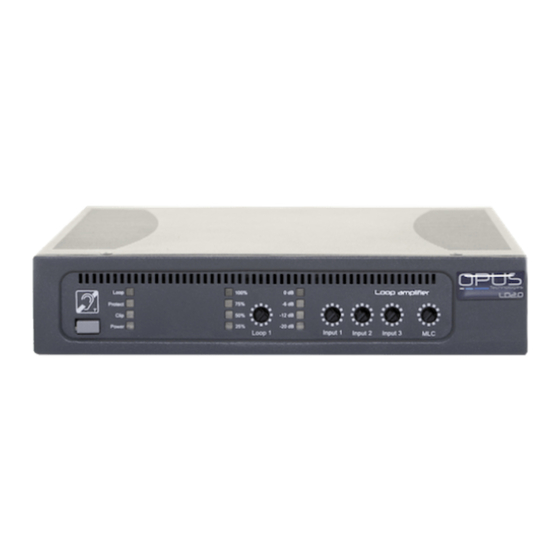
Page 9: Front Panel And Settings
LD Series | Installation and user manual | 4.3 Front panel and settings Front Panel- Figure 4 1. LED «Protect», fault display. This LED is displayed when the power amplifier, loop or priority input is in fault. 2. LED "Loop", presence of loop. This LED is displayed when the loop is cut or its impedance is not suitable 3. -
Page 10: Back Side And Settings
LD Series | Installation and user manual | 4.4 Back side and settings Back Side - Figure 5 14. Audio Input n°1 Combo: Mic or Line. This input is used to connect external audio inputs from a line-level source (mixer, preamp, etc.) or a microphone. The Combo connector accepts an XLR or a 6.35 jack. -
Page 11: Racking
LD Series | Installation and user manual | 4.5 Racking 4.5.2 Rack integration 4.5.1 Ventilation and rack mounting Necessary accessory: Fixing kit OP-R * For better ventilation leave a space of 1U Secure the rack mounting brackets as shown in (44mm) above the amplifier. - Page 12 LD Series | Installation and user manual | Illustration of two amplifiers racking 4.5.3 Integrating an amplifier on a wall Option required: OP-R * Fixation Kit Fasten the brackets as shown in the picture using the screws provided in the kit.
- Page 13 Pin 2 : Hot spot Pin 3 : Cold spot 4.6.3 Priority 100V input Asymmetric : Input 1 (100V) of the LD series amplifiers are Pin 1 : Mass made to prioritize PA systems in order to Pin 2 : Signal facilitate evacuation situations.
-
Page 14: Adjustments And Connections
LD Series | Installation and user manual | 4.6 Adjustments and connections 4.6.9 Power on Loop Protect Clip Power The unit is powered up using the gray switch on the front panel of the amplifier. If the amplifier is powered, the Power LED lights in blue. - Page 15 LD Series | Installation and user manual | 4.7 Connections of two amplifiers 4.7.1 Slave over master Slave Amplifier Master Amplifier 90° output to slave Master Input amplifier For using of in a low overspill or high coverage system : 1.
- Page 16 LD Series | Installation and user manual | 4.7.2 Slave over slave Slave amplifier 1 Master amplifier 90° output to slave amplifier Input to slave amplifier and 0° output to slave amplifier Slave amplifier 3 Slave amplifier 2 Input to slave amplifier 2 Input to slave amplifier 3 and 90°...
-
Page 17: Setting Up
6.3.2 and 6.3.3. 5.2.3 Final adjustments Depending on the type of amplifier of the LD series, 14. Connect the two loops and then adjust the the settings will be made differently:... -
Page 18: Metal Loss Compensation Adjustment
LD Series | Installation and user manual | 5.4 Metal loss compensation adjustment 5.6.2 Phantom power If you detect a distortion of the With the DIP switch on the rear panel of the signal due to magnetic pollution, amplifier (see you can turn on or off the... -
Page 19: Understanding And Planning Of A Loop System
LD Series | Installation and user manual | 6. Understanding and planning of a loop 6.2.2 Diffusion of the magnetic field in a loop system When the intensity of the current flowing in a loop is 6.1 Preamble adapted to the width of the room to be equipped,... -
Page 20: The Different Types Of Implantation
LD Series | Installation and user manual | 6.2.3 Composition of a system 6.3.2 The simple loop in the “8” form A magnetic induction loop system is composed of: • An amplifier In some configurations, it will be preferable to use •... - Page 21 LD Series | Installation and user manual | 6.3.3 Phased loops with low overspill 6.3.2 Phased simple loops In order to allow more coverage in large spaces When several rooms are contiguous to each other, it is important to take into account the external such as an exhibition park, a gym or a zenith, it radiation of the magnetic field.
-
Page 22: The Magnetic Induction Loop
LD Series | Installation and user manual | 7. The magnetic induction loop 7.3 The magnetic field Installing a magnetic induction loop is a complex At 1.2m above ground level in the area surrounded exercise. To ensure that it works properly, it is... -
Page 23: Loop Layouts Simulation
LD Series | Installation and user manual | 7.5 Loop layouts simulation Magnetic field necessary to cover for a 15x10m room. Data from Opus Smartloop simulation tool. 1. Simple loop: Simple loop layout 2D view of a simple loop magnetic field... - Page 24 LD Series | Installation and user manual | 7.5 Loop layouts simulation Magnetic field necessary to cover for a 15x10m room. Data from Opus Smartloop simulation tool. 2. Cancellation loop: Cancellation loop layout 2D view of a cancellation loop magnetic field...
- Page 25 LD Series | Installation and user manual | 7.5 Loop layouts simulation Magnetic field necessary to cover for a 15x10m room. Data from Opus Smartloop simulation tool. 3. Ultra-low spill system : Ultra-low spill system layout 2D view of an ultra-low spill sytem magnetic field...
-
Page 26: Installation Constraints
LD Series | Installation and user manual | 8. Installation constraints 9. Warranty and after-sales service Some environments may interfere with magnetic Opus Technologies amplifiers loops, here are the main causes: manufactured in France according to strict specifications guaranteeing quality 8.1 External overspill... -
Page 27: Certificate Of Conformity To Iec 60118-4 Standard
LD Series | Installation and user manual | User Manual... - Page 28 Certificate of conformity IEC60118-4 AFILS installation for accessibility of hearing impaired people in publicvenues Costumer Informations Installer Informations Client : Installer : Room : Company : Adresse : Device : Serial Number : Tested by : ROOM SKETCH Draw the room and the coverage area indicating measurement points and background noise SEARCH FOR BACKGROUND NOISE ANDINTERFERENCES Amplifier off and OP-FSM in "-20dB"...
- Page 29 NOTES...
- Page 30 For any questions, contact us. OPUS TECHNOL£OGIES — ZI Lagrange II — 9 Chemin de la Vieille Ferme — 33650 MARTILLAC Tel: (+33)09.81.24.00/06. — Fax: (+33)09.82.63.22.56. — contact@opus-technologies.fr 09/2018 User Manual...
Need help?
Do you have a question about the LD Series and is the answer not in the manual?
Questions and answers