Opus Technologies LD Series Installation And User Manual
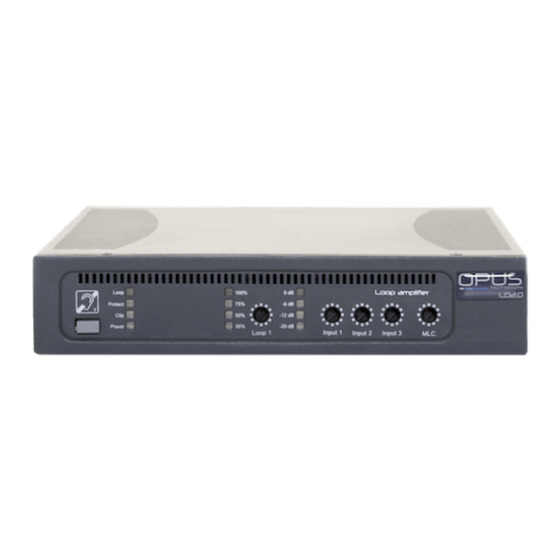
1-channel loop amplifier
Hide thumbs
Also See for LD Series:
- Installation and user manual (30 pages) ,
- Installation and user manual (72 pages)

Subscribe to Our Youtube Channel
Related Manuals for Opus Technologies LD Series


Summary of Contents for Opus Technologies LD Series
- Page 1 Class D loop amplifier LD SERIES 1-CHANNEL LOOP AMPLIFIER Installation and user manual LD 1.0 / 2.0 / 3.0...
- Page 2 LD Series | Installation and user manual User manual...
-
Page 3: Table Of Contents
LD Series | Installation and user manual TABLE OF CONTENTS| EN 1. Introduction 1.1 Purpose 1.2 Target audience 1.3 Alerts 1.4 Icons 2. Loop amplifier presentation 2.1 Description 2.2 The range 2.3 Package contents 2.4 Rack mounting kit: OP-R (optional) 2.5 Advice and safety... - Page 4 LD Series | Installation and user manual TABLE OF CONTENTS| EN 7. The magnetic induction loop 7.1 Installing your loop 7.2 Cable section 7.3 Connection 7.4 The magnetic field 7.5 Technical study 8. Installation constraints 8.1 Magnetic overspill 8.2 Metal distortion 9.
-
Page 5: Introduction
1.4 Icons 1.4.1 Note Icons Thank you for having purchased an Opus Technologies LD SERIES class D loop amplifier. Please take a few moments to read this manual, it will ensure the Warning icons used with the notes provide additional optimal use of the product and many years of flawless information about the note. -
Page 6: Loop Amplifier Presentation
If possible, give the delivery note number and a The LD Series has been developed with strict and tracking number. rigorous specifications that allow us to offer a 5 year warranty. The products have been designed with options to facilitate their use and installation. -
Page 7: Advice And Safety
LD Series | Installation and user manual 2.5 Advice and safety • The device may only be operated by trained Most of defective loop installations are the result of staff qualified for loop installation. a lack of preparation. Take your time before starting •... -
Page 8: Technology Presentation
LD Series | Installation and user manual 3. Technology presentation The audio source can come from various origins. In a cinema, for example, the sound of the film will be transmitted. In a conference room, the sound of the 3.1 What is an AFILS (Audio Frequency speaker's microphone will be transmitted. -
Page 9: Controls, Connections And Adjustments
LD Series | Installation and user manual 4. Controls, connections and adjustments 4.1 Control The amplifiers comes with a fault synthesis allowing you to monitor the main functions of the unit, such as the amplifier’s power, the integrity of the loop cable connected to the amplifier and the inputs. -
Page 10: Front Panel And Adjustments
LD Series | Installation and user manual 4.3 Front panel and adjustments Front panel - Figure4 1. "Protect" LED, fault summary display. Error indicator. This red LED lights up when the master loop amplifier is overloaded, when the input level of the master loop is too high or when the master loop is defective. -
Page 11: Rear Panel And Adjustments
17. INPUT 1 Phoenix type terminal block: 100V priority. This terminal block input allows you to connect an external audio input from a 100V sound system, the audio is directly recovered from the speaker’s line. 18. Slave IN input. This input is used to connect a 0° or 90° output (Master/Slave) from another LD series loop amplifier. -
Page 12: Rack Mounting
LD Series | Installation and user manual 4.5 Rack mounting 4.5.2 Rack integration 4.5.1 Ventilation and rack mounting Required accessory: OP-R* mounting kit For better ventilation we recommend leaving a space Attach the rack mounting brackets as shown below of 1U (44 mm) above the amplifier. - Page 13 LD Series | Installation and user manual 4.5.3 Rack-mounting two loop amplifiers 4.5.4 Mounting the loop amplifier on a wall Required accessory: OP-R* mounting kit Required accessory: OP-R* mounting kit Attach the mounting brackets as shown below (Figure 9) Attach the rack mounting brackets as shown below using the screws provided in the kit.
-
Page 14: Adjustment And Connection
The status output is used to send a status of the loop amplifier to external devices via a NO/NC relay. 4.6.3 Priority INPUT 1 100V input 4.6.8 Connectors The INPUT 1 (100V) of the LD series amplifiers has a 3 pin-XLR priority for security sound systems in case of Symmetric: evacuation of the building. - Page 15 LD Series | Installation and user manual 4.6 Adjustment and connection 4.6.11 Protect and Clip LEDs 4.6.9 Switching on The " Protect " and " Clip " LEDs light up if : • The ohmic resistance of the inductive loop is Loop not between 0.5 and 3 Ohm.
-
Page 16: Connecting Two Amplifiers
90° output to Slave Input on slave amplifier amplifier To expand and duplicate an installation or to use a low spill system or high coverage system with the LD Series 1-channel amplifiers: 1. Connect the loops to the terminals provided: amplifier Loop terminal. - Page 17 LD Series | Installation and user manual 4.7.2 Master to several slaves Master amplifier Slave 1 amplifier 90° output to Input on slave 1 amplifier Slave amplifier and 0° output to slave amplifier Slave 2 amplifier Slave 3 amplifier Input on slave 2...
-
Page 18: Setup
6.3.2 and 6.3.3. Depending on the type of LD series amplifier, the 5.2.2 Slave loop amplifier settings will be different: 8. Turn on your amplifier and check that all the potentiometers are at 0 level •... -
Page 19: Securing Settings
LD Series | Installation and user manual 5.2.3 Final adjustments If the fault synthesis detects an operating problem (broken loop, wrong loop impedance, amplifier failure, etc.) the NO/NC relay is deactivated in the 13. Connect the two loops and then adjust the normally open position: NO. -
Page 20: Functioning And Planning Of A Loop System
LD Series | Installation and user manual 6. Functioning and planning of a loop system 6.2.2 Magnetic field diffusion in a loop When the intensity of the current flowing in a loop is 6.1 Preamble adapted to the width of the room to be equipped, the... -
Page 21: The Different Types Of Installation
LD Series | Installation and user manual 6.3.2 The simple 8 loop or phased array 6.2.3 System composition A magnetic induction loop system is composed of In some configurations, it will be preferable to use an 8 loop rather than a single loop to generate a more intense magnetic field on the surface to be covered. - Page 22 LD Series | Installation and user manual 6.3.3 Simple phased loops 6.3.4 Phased loops with low overflow When several rooms are adjacent to each other (one In order to allow a more extensive coverage in large next to each other or one on top of each other), it is...
-
Page 23: The Magnetic Induction Loop
LD Series | Installation and user manual 7. The magnetic induction loop The Loop Cable (LC-50/100/150) offers a variation of sections from 0.5 to 2.5mm². See image below: The installation of a magnetic induction loop is a complex exercise. To ensure that it works perfectly, it... -
Page 24: Technical Study
LD Series | Installation and user manual 7.5 Technical study Presentation of magnetic field data for a 15x10m room. Data from our simulation tool Opus Smartloop. 7.5.1 Perimeter loop Simple loop installation Simple loop 2D simulation Simple loop median Simple loop 3D simulation... - Page 25 LD Series | Installation and user manual 7.5 Technical study Presentation of magnetic field data for a 15x10m room. Data from our simulation tool Opus Smartloop. 7.5.2 Cancellation loop Cancellation loop installation Cancellation loop 2D simulation Cancellation loop median Cancellation loop 3D simulation...
- Page 26 LD Series | Installation and user manual 7.5 Technical study Presentation of magnetic field data for a 15x10m room. Data from our simulation tool Opus Smartloop. 7.5.3 Ultra low overflow system Ultra low overflow system installation Ultra low overflow system 2D simulation...
-
Page 27: Installation Constraints
LD Series | Installation and user manual 8. Installation constraints Some environments can create interference with the magnetic induction loops, here are the main causes. 8.1 Magnetic overspill The installation of a perimeter loop system is perfectly suitable to cover a room if the amplifier is correctly... -
Page 28: Information
Note: Disconnect the LD series amplifier from the technologies.fr. power supply first. Never use spirits, thinners or other organic solvents. Do not place the LD series amplifier where it will be exposed to full sunlight for long periods. In addition, it must be protected 9.4. -
Page 29: Technical Specifications
LD Series | Installation and user manual 9.5. Technical specifications LD1.0 LD2.0 LD3.0 Coverage 250 m² (10*25 m²) 450 m² (15*30 m²) 1000 m² (20*45 m²) Operating 0 to +45°C 0 to +45°C 0 to +45°C temperature Storage temperature -30 to +70°C -30 to +70°C... -
Page 30: Ce Certification
LD Series | Installation and user manual 9.5. Technical specifications LD1.0 LD2.0 LD3.0 OUTPUT Loop impedance 0,5Ω à 3Ω 0,5Ω à 3Ω 0,5Ω à 3Ω Output voltage 34V rms (48V pK) 34V rms (48V pK) 34V rms (48V pK) Peak current... -
Page 31: Certificate Of Conformity To The Iec-60118-4 Standard
LD Series | Installation and user manual User manual... - Page 32 Certificatde conformité IEC60118-4 Installation de boucle àinduction magnétiquepour malentendants Informations Client Informations surl’installation Client : Installateur : Salle: Société : Adresse: Équipement : N° série: Testée par: CROQUIS DE LASALLE Dessinerla salle etla zonede couvertureenindiquantlespoints de mesureetles bruits de fond RECHERCHE DE BRUITS DE FOND ET INTERFÉRENCES Amplificateuréteint etOP-FSM en position«...
- Page 33 NOTES...
- Page 34 NOTES...
- Page 35 NOTES...
- Page 36 For any additional questions, please contact us. OPUS TECHNOL£OGIES — ZI Lagrange II — 9 Chemin de la Vieille Ferme — 33650 MARTILLAC Tel: (+33)09.81.24.00/06. — Fax: (+33)09.82.63.22.56. — contact@opus-technologies.fr 03/2021 User manual...
Need help?
Do you have a question about the LD Series and is the answer not in the manual?
Questions and answers