Advertisement
Quick Links
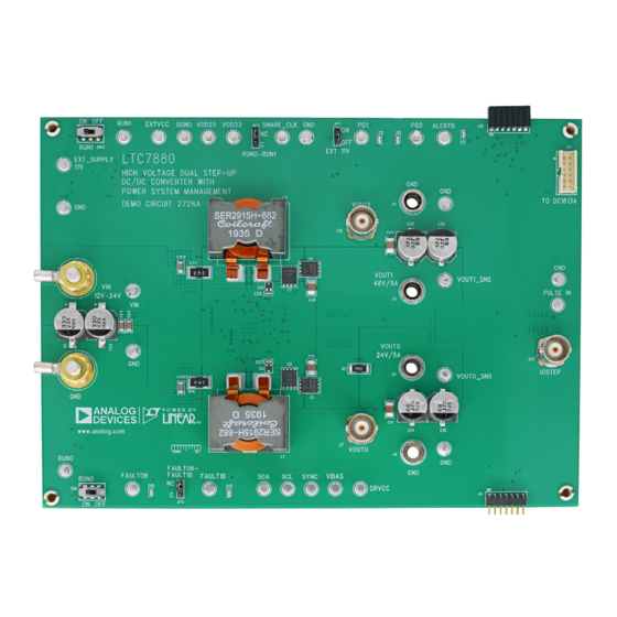
High Voltage Dual Step-up DC/DC Converter
DESCRIPTION
Demonstration circuit 2728A is a high voltage, dual output
boost converter with 12V to 24V input range. The output
voltage is adjustable from V
supply 5A maximum load current. The demo board has a
LTC
7880
controller, which is a 60V dual output step-up
®
controller with digital power system management. Please
see LTC7880 data sheet for more detailed information.
DC2728A powers up to default settings and produces
power based on configuration resistors or its nonvola-
tile memory (NVM) without the need for any serial bus
communication. This allows easy evaluation of the DC/
DC converter. To fully explore the extensive power sys-
tem management features of the part, download the GUI
BOARD PHOTO
with Digital Power System Management
to 48V. Each output can
IN
Figure 1. Dual Output LTC7880/DC2728A Demo Circuit
DEMO MANUAL DC2728A
software LTpowerPlay
onto your PC and use ADI's I
®
SMBus/PMBus dongle DC1613A to connect to the board.
LTpowerPlay allows the user to reconfigure the part on-
the-fly and store the configuration in EEPROM, view
telemetry of voltage, current, temperature and fault status.
GUI Download
The software can be downloaded from:
LTpowerPlay
For more details and instructions of LTpowerPlay, please
refer to LTpowerPlay GUI for LTC7880 Quick Start Guide.
Design files for this circuit board are
All registered trademarks and trademarks are the property of their respective owners.
LTC7880
2
C/
available.
Rev. 0
1
Advertisement

Related Manuals for Linear Technology Analog Devices DC2728A


Summary of Contents for Linear Technology Analog Devices DC2728A
- Page 1 DEMO MANUAL DC2728A LTC7880 High Voltage Dual Step-up DC/DC Converter with Digital Power System Management DESCRIPTION Demonstration circuit 2728A is a high voltage, dual output software LTpowerPlay onto your PC and use ADI’s I ® boost converter with 12V to 24V input range. The output SMBus/PMBus dongle DC1613A to connect to the board.
-
Page 2: Performance Summary
DEMO MANUAL DC2728A PERFORMANCE SUMMARY Specifications are at T = 25°C PARAMETER CONDITIONS VALUE Input Voltage Range 12V to 24V Output Voltage, V = 12V to 24V, I = 0A to 5A 24V to 48V, Default: 24V OUT0 OUT0 Maximum Output Current, I = 12V to 24V, V = 24V to 48V OUT0... - Page 3 DEMO MANUAL DC2728A QUICK START PROCEDURE Figure 2. Proper Measurement Equipment Setup Figure 3. Proper Measurement Equipment Setup Rev. 0...
- Page 4 DEMO MANUAL DC2728A QUICK START PROCEDURE Connecting a PC to DC2728A sequencing parameters, the fault log, fault responses, GPIOs and other functionalities. The DC1613A dongle You can use a PC to reconfigure the power management may be plugged when V is present.
- Page 5 DEMO MANUAL DC2728A QUICK START PROCEDURE OUT0 OUT1 20MHz BW 20MHz BW 200mV/DIV 200mV/DIV 0A TO 1.25A 0A TO 1.25A LOAD STEP LOAD STEP dc2728A F08 500 s/DIV 500 s/DIV dc2728A F07 Figure 7. V Load Transient Response at V = 12V, V = 24V Figure 8.
- Page 6 DEMO MANUAL DC2728A LTPOWERPLAY SOFTWARE GUI LTpowerPlay is a powerful Windows-based development issues when bringing up rails. LTpowerPlay utilizes the environment that supports Analog Devices power sys- DC1613A USB-to-SMBus controller to communicate tem management ICs and μModule products, including with one of many potential targets, including LTM4675, ®...
- Page 7 DEMO MANUAL DC2728A LTPOWERPLAY QUICK START PROCEDURE The following procedure describes how to use LTpowerPlay d. If you want to change the output voltage to a differ- to monitor and change the settings of LTC7880. ent value, like 36V. In the Config tab, type in 36 in the VOUT_COMMAND box, like this: 1.
- Page 8 DEMO MANUAL DC2728A PARTS LIST ITEM REFERENCE PART DESCRIPTION MANUFACTURER/PART NUMBER Required Circuit Components C1, C85 CAP ., 330μF, HYBRID, 35V, 20%, SMD PANASONIC, EEHZK1V331P C3, C37, C38 CAP ., 2.2μF, X5R, 50V, 10%, 0603 MURATA, GRM188R61H225KE11D C4, C5, C27, C33 CAP ., 0.01μF, X7R, 100V, 10%, 0603 AVX, 06031C103KAT2A C6, C13, C28...
-
Page 9: Parts List
DEMO MANUAL DC2728A PARTS LIST ITEM REFERENCE PART DESCRIPTION MANUFACTURER/PART NUMBER C79, C80 CAP ., 100μF, X5R, 16V, 20%, 1210 TAIYO YUDEN, EMK325ABJ107MM-T CAP ., 220pF, X7R, 50V, 10%, 0603 AVX, 06035C221KAT2A C82, C83 CAP ., 0.01μF, X7R, 100V, 10%, 0603 AVX, 06031C103KAT2A CAP ., 0.1µF, 20%, 25V, X5R, 0603 AVX, 06033D104KAT2A... - Page 10 DEMO MANUAL DC2728A PARTS LIST ITEM REFERENCE PART DESCRIPTION MANUFACTURER/PART NUMBER Hardware: For Demo Board Only E1-E8, E11, E14, E18, E20-E27, E29, TEST POINT, TURRET, 0.094, MTG. HOLE MILL-MAX, 2501-2-00-80-00-00-07-0 E30, E32, E35-E40 JP1, JP2, JP3 CONN.,HDR,MALE,1×3, 2mm, THT, STR WURTH ELEKTRONIK, 62000311121 J1, J2 STUD, FASTENER, #10-32...
-
Page 11: Schematic Diagram
DEMO MANUAL DC2728A SCHEMATIC DIAGRAM Rev. 0... - Page 12 DEMO MANUAL DC2728A SCHEMATIC DIAGRAM Rev. 0...
- Page 13 DEMO MANUAL DC2728A SCHEMATIC DIAGRAM Rev. 0 Information furnished by Analog Devices is believed to be accurate and reliable. However, no responsibility is assumed by Analog Devices for its use, nor for any infringements of patents or other rights of third parties that may result from its use. Specifications subject to change without notice.
- Page 14 DEMO MANUAL DC2728A ESD Caution ESD (electrostatic discharge) sensitive device. Charged devices and circuit boards can discharge without detection. Although this product features patented or proprietary protection circuitry, damage may occur on devices subjected to high energy ESD. Therefore, proper ESD precautions should be taken to avoid performance degradation or loss of functionality. Legal Terms and Conditions By using the evaluation board discussed herein (together with any tools, components documentation or support materials, the “Evaluation Board”), you are agreeing to be bound by the terms and conditions set forth below (“Agreement”) unless you have purchased the Evaluation Board, in which case the Analog Devices Standard Terms and Conditions of Sale shall govern.
Need help?
Do you have a question about the Analog Devices DC2728A and is the answer not in the manual?
Questions and answers