
Related Manuals for Helios RL 100


Summary of Contents for Helios RL 100
- Page 1 Helios Ventilatoren MONTAGE- UND BETRIEBSVORSCHRIFT INSTALLATION AND OPERATING INSTRUCTIONS Rohbaupaket Laibung Installation Kit Soffit RL 100/125...
-
Page 2: Table Of Contents
Montage- und Betriebsvorschrift Rohbaupaket Laibung RL 100/125 DEUTSCH Inhaltsverzeichnis KAPITEL 1 SICHERHEIT . . . . . . . . . . . . . . . . . . . . . . . . . . . . . . . . . . . . . . . . . . . . . . . . . . . . . . . . . . . . . . . . . . . . . Seite 2 Wichtige Informationen . -
Page 3: Wichtige Informationen
Betrieb des Lüftungsgerätes zu gewährleisten. Alle anlagenbezogenen Sicherheitsvorschriften müssen eingehalten werden. Diese Montage- und Betriebsvorschrift gilt für das Rohbaupaket Laibung RL 100/125 sowie die dazugehörigen Wand- gitter Laibungselement KWL 45 LG... als Bestandteile des Zuluftautomaten Laibungslement ZLA LE welcher aus meh- reren Komponenten besteht. -
Page 4: Einlagerung
Montage- und Betriebsvorschrift Rohbaupaket Laibung RL 100/125 2 .4 Einlagerung Der Lagerort muss erschütterungsfrei, wassergeschützt und frei von Temperaturschwankungen sein. Schäden, deren Ursache in unsachgemäßem Transport, Einlagerung oder Inbetriebnahme liegen, sind nachweisbar und unterliegen nicht der Gewährleistung. KAPITEL 3 3 .0 Lieferumfang Das Rohbaupaket Laibung erst unmittelbar vor dem jeweiligen Montageschritt bzw. -
Page 5: Einbauübersicht Laibungselement
Montage- und Betriebsvorschrift Rohbaupaket Laibung RL 100/125 4 .0 Einbauübersicht Laibungselement KAPITEL 4 Anforderungen Einbau Laibungselement: POSITIONIERUNG/ 1. Wandstärke der Rohbauwand: mind. 190 mm bis max. 480 mm EINBAU 2. Dämmplattenstärke: mind. 100 mm 3. Horizontaler Abstand der Kernbohrung zur Laibung (Fertigputz): mind. 220 mm bis max. 500 mm (s. Abb. 6) 4. -
Page 6: Positionierung (Kernbohrung)
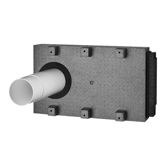
4 .2 Einbau Laibungselement Montagevorbereitungen: – Für die Installation wird eine Kernbohrung benötigt: RL 100: Ø ≥112 mm RL 125: Ø ≥132 mm 1. Position der Kernlochbohrung für das Laibungselement bestimmen (s. Abb. 6). 2. Kernlochbohrung ausführen. 3. Abmaße für Teleskoprohr und Laibungselement bestimmen (s. Kapitel 4.0 Einbauübersicht Laibungselement). -
Page 7: Montageschritte Aussenwand
Montage- und Betriebsvorschrift Rohbaupaket Laibung RL 100/125 m Beim Einbau des Teleskoprohrs ist darauf zu achten, dass dieses mit einem leichten Gefälle nach außen HINWEIS verlegt wird, so dass bei einem starken Schlagregen eintretendes Wasser nicht in den Innenraum fließen kann . - Page 8 Montage- und Betriebsvorschrift Rohbaupaket Laibung RL 100/125 Abb .10 8. Dünne Kleber-/Dichtmittelraupe auf den Putzrahmen aufbringen (Abb.11). 9. Putzrahmen auf das Laibungselement aufstecken und mit den beigelegten Dämmstoffdübeln anschrauben (Abb. 11/12). Abb .11 Abb .12 10. Laibungselement hinterschäumen. 11. Umliegenden Dämmplatten anbringen (Abb.13).
- Page 9 Montage- und Betriebsvorschrift Rohbaupaket Laibung RL 100/125 15. Kondensatwanne einstecken (Abb.15). Abb .15 16. Wandgitter montieren (Abb.16). Die Schrauben sind im Lieferumfang enthalten. Abb .16...
- Page 10 Installation and Operating Instructions Installation Kit Soffit RL 100/125 ENGLISH Table of Contents CHAPTER 1 SAFETY . . . . . . . . . . . . . . . . . . . . . . . . . . . . . . . . . . . . . . . . . . . . . . . . . . . . . . . . . . . . . . . . . . . . . . . Page 2 Important information .
-
Page 11: Chapter 1 Safety
1 .3 Area of application The installation kit soffit RL 100/125 and the wall grille soffit element KWL 45 LG.. are used as components of the supply air unit soffit element ZLA LE. A completely configured supply air unit also consists of an inner panel. Furthermore, a sound insulation element is available for the soffit channel, as well as an insect screen and sound insulation elements for the duct and flow rate stabiliser. -
Page 12: Storage
Installation and Operating Instructions Installation Kit Soffit RL 100/125 2 .4 Storage The storage place must be vibration-free, waterproof and free of temperature variations. Damages due to improper transportation, storage or commissioning are not covered by warranty. CHAPTER 3 3 .0... -
Page 13: Chapter 4 Positioning / Assembly
Installation and Operating Instructions Installation Kit Soffit RL 100/125 4 .0 Installation overview soffit element CHAPTER 4 Installation requirements soffit element: POSITIONING/ 1. Wall thickness of uncovered wall: min. 190 mm to max. 480 mm ASSEMBLY 2. Insulation panel thickness: min. 100 mm 3. -
Page 14: Positioning (Core Drilling)
Installation and Operating Instructions Installation Kit Soffit RL 100/125 SCHNITT A-A Fig . 5 min. Inside 260 mm Outside Aussen Innen Uncovered wall Rohbauwand Telescopic duct (ohne Dämmung) (without insulation) Teleskoprohr Internal duct Innenrohr zur Raumseite Installation foam Montageschaum to room side 30 - 70 ±3... -
Page 15: Installation Step External Wall
Installation and Operating Instructions Installation Kit Soffit RL 100/125 m When installing the telescopic duct, it must be ensured that it is installed with a slight gradient to the NOTE outside, so that water cannot flow into the internal space in case of heavy rain . - Page 16 Installation and Operating Instructions Installation Kit Soffit RL 100/125 Fig .10 8. Apply thin glue/sealing beads to the plaster frame (Fig.11). 9. Connect plaster frame to the soffit element and screw in with the enclosed insulation fixings (Fig. 11/12). Fig .11 Fig .12...
- Page 17 Installation and Operating Instructions Installation Kit Soffit RL 100/125 15. Insert condensate tray (Fig.15). Fig .15 16. Mount wall grille (Fig.16). The screws are included in the scope of delivery. Fig .16...
- Page 18 Installation and Operating Instructions Installation Kit Soffit RL 100/125...
- Page 19 Installation and Operating Instructions Installation Kit Soffit RL 100/125...
- Page 20 HELIOS Ventilatoren GmbH + Co KG · Lupfenstraße 8 · 78056 VS-Schwenningen HELIOS Ventilateurs · Le Carré des Aviateurs · 157 avenue Charles Floquet · 93155 Le Blanc Mesnil Cedex CH HELIOS Ventilatoren AG · Tannstrasse 4 · 8112 Otelfingen GB HELIOS Ventilation Systems Ltd.
Need help?
Do you have a question about the RL 100 and is the answer not in the manual?
Questions and answers