Dell SC5020 Setting-Up Manual
Hide thumbs
Also See for SC5020:
- Getting started manual (16 pages) ,
- Setting up (2 pages) ,
- Setting up your system (2 pages)
Advertisement
Quick Links
Setting Up a Dell SC5020 and SC5020F Storage System
1
Before You Begin
Warning!
Before you set up and operate your Dell storage system, review the safety instructions that came with the
storage system.
Unpack Storage Center Equipment
Develop a Configuration Plan
An SC5020 and SC5020F storage system includes:
Before installing the storage hardware, develop a configuration plan where you can record host
•
Documentation
server information, switch information, and network information.
•
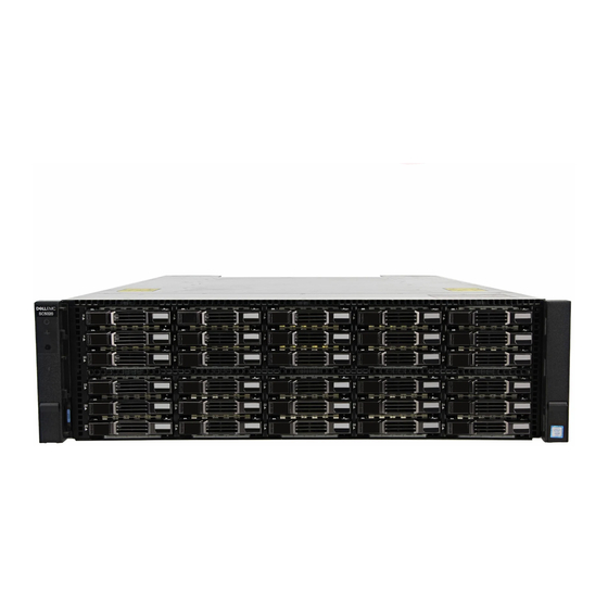
Storage system with drives
Record System Information
•
Rack rails
•
System management IPv4 address for Storage Center
•
USB cables (2)
•
IPv4 address of the MGMT port on each storage controller
•
Power cables (2)
•
Domain name
•
Front bezel
•
DNS server address
•
Additional IPv4 addresses if the storage system has iSCSI I/O ports
Consider Plans for Multipath/Failover
Redundancy is provided by fault domains, which allow alternate paths if a path fails. Fault
domains are determined by the number of independent Fibre Channel fabrics or iSCSI networks.
Each switch carries a separate fault domain. If a port fails, any port within the same fault domain
takes over for the failed port. Dell recommends using multipathing, so that volumes are mapped
to ports in more than one fault domain.
More Information
For operating system, host bus adapter (HBA), and switch requirements, rFor a list of supported
HBA or NIC drivers and firmware, refer to the Dell Storage Compatibility Matrix located in the
Knowledge Base at
4
Cable the Host Servers to the Storage System
The SC5020 storage system supports Fibre Channel, iSCSI, or SAS protocols to connect the Storage Center to host servers. The SC5020F storage system supports Fibre Channel or iSCSI protocols to connect the Storage Center to host servers.
Fault domains provide fault tolerance at the storage controller level. If you are using Fibre Channel, incorporate your switch zoning strategy with the fault domains. Use redundant cabling to avoid a single point of failure.
1.
Identify the protocol being used to connect the host servers to the storage system.
2. Refer to the diagram below that corresponds to the proper protocol. These cabling guidelines ensure the configuration has redundancy and failover capability. For more information, contact Dell Technical Support.
Fibre Channel and iSCSI HBA Cabling
Install the Fibre Channel or iSCSI HBAs in the host servers and connect the host servers and storage
system to the corresponding Fibre Channel or Ethernet switches.
Fibre Channel 4 Port Configuration
iSCSI 4 Port Configuration
1.
For Fibre Channel 4 Port configurations, install Fibre
Channel HBAs into the host servers.
For iSCSI 4 Port configurations, install iSCSI HBAs or
network interface controllers (NICs) dedicated for iSCSI
traffic into the host servers.
2. Connect each host server to the two switches.
– Connections shown in orange belong to fault domain 1.
– Connections shown in blue belong to fault domain 2.
3. Connect fault domain 1 (in orange) to switch 1.
– Top storage controller: port 1 to switch 1
– Top storage controller: port 3 to switch 1
– Bottom storage controller: port 1 to switch 1
– Bottom storage controller: port 3 to switch 1
4. Connect fault domain 2 (in blue) to switch 2.
– Top storage controller: port 2 to switch 2
– Top storage controller: port 4 to switch 2
– Bottom storage controller: port 2 to switch 2
– Bottom storage controller: port 4 to switch 2
Fibre Channel 2 Port Configuration
iSCSI 2 Port Configuration
1.
For Fibre Channel 2 Port configurations, install Fibre
Channel HBAs into the host servers.
For iSCSI 2 Port configurations, install iSCSI HBAs or
NICs dedicated for iSCSI traffic into the host servers.
2. Connect each host server to the two switches.
– Connections shown in orange belong to fault domain 1.
– Connections shown in blue belong to fault domain 2.
3. Connect fault domain 1 (in orange) to switch 1.
– Top storage controller: port 1 to switch 1
– Bottom storage controller: port 1 to switch 1
4. Connect fault domain 2 (in blue) to switch 2.
– Top storage controller: port 2 to switch 2
– Bottom storage controller: port 2 to switch 2
www.dell.com/support.
iSCSI Mezzanine Card Cabling
If the storage system includes an iSCSI mezzanine card, connect the
host servers and storage system to Ethernet switches.
iSCSI 4 Port Mezzanine Card Configuration
1.
Connect each host server to the two Ethernet switches.
– Connections shown in orange belong to fault domain 1.
– Connections shown in blue belong to fault domain 2.
2. Connect fault domain 1 (in orange) to switch 1.
– Top storage controller: port 1 to switch 1
– Top storage controller: port 3 to switch 1
– Bottom storage controller: port 1 to switch 1
– Bottom storage controller: port 3 to switch 1
3. Connect fault domain 2 (in blue) to switch 2.
– Top storage controller: port 2 to switch 2
– Top storage controller: port 4 to switch 2
– Bottom storage controller: port 2 to switch 2
– Bottom storage controller: port 4 to switch 2
2
Mount the Chassis and Optional Enclosures
Warning!
The chassis is heavy. Do not attempt to lift the chassis
without assistance.
Use the racking instructions included with your package to mount the chassis.
Mount the storage system chassis and expansion enclosures in a manner that allows
for expansion in the rack and prevents the rack from becoming top-heavy. Secure the
storage system chassis to the rack using the mounting screws that are located behind
the latches on each chassis ear. Dell recommends mounting the storage system chassis
in the bottom of the rack.
SAS HBA Cabling
Install the SAS HBAs in the host servers and directly connect the
host servers to the storage system.
NOTE:
The SC5020F storage system does not support
front-end SAS connectivity.
SAS 4 Port Configuration
1.
Install SAS HBAs in the host servers.
2. Connect fault domain 1 (in orange) to server 1.
– Top storage controller: port 1 to port on server 1
– Bottom storage controller: port 1 to port on server 1
3. Connect fault domain 2 (in blue) to server 2.
– Top storage controller: port 2 to port on server 2
– Bottom storage controller: port 2 to port on server 2
4. Connect fault domain 3 (in gray) to server 3.
– Top storage controller: port 3 to port on server 3
– Bottom storage controller: port 3 to port on server 3
5. Connect fault domain 4 (in red) to server 4.
– Top storage controller: port 4 to port on server 4
– Bottom storage controller: port 4 to port on server 4
3
Install the Front Bezel
1.
Hold the bezel with the logo upright.
2. Hook the right end of the bezel into the right side of the chassis.
3. Swing the left end of the bezel toward the left side of the chassis.
4. Press the bezel into place until the release latch closes.
5. Use the key to lock the front bezel.
5
Connect to Management Network
The Ethernet management interface of each storage controller must be
connected to a management network. The Ethernet management port
provides access to the Storage Center and is used to send emails, alerts,
SNMP traps, and support data.
1.
Connect the Ethernet management port on the top storage
controller to the Ethernet switch.
2. Connect the Ethernet management port on bottom storage
controller to the Ethernet switch.
Advertisement

Related Manuals for Dell SC5020


Summary of Contents for Dell SC5020
- Page 1 Cable the Host Servers to the Storage System The SC5020 storage system supports Fibre Channel, iSCSI, or SAS protocols to connect the Storage Center to host servers. The SC5020F storage system supports Fibre Channel or iSCSI protocols to connect the Storage Center to host servers.
- Page 2 Cable the Expansion Enclosures Connect Power Cables to the Storage System To add capacity to an SC5020 storage system, you can connect SC400, SC420, or SC460 expansion enclosures. To add capacity to an SC5020F storage system, you can connect SC420F expansion enclosures. CAUTION: Make sure that the power switches are in the OFF position before connecting the power cables.
Need help?
Do you have a question about the SC5020 and is the answer not in the manual?
Questions and answers