Samsung AR Series User Manual
Hide thumbs
Also See for AR Series:
- Technical data book (52 pages) ,
- User manual (33 pages) ,
- User manual (13 pages)
Table of Contents
Advertisement
Advertisement
Table of Contents

Related Manuals for Samsung AR Series


Summary of Contents for Samsung AR Series
-
Page 2: Table Of Contents
Table of Contents Safety Precautions ................User Manual Unit Specifications and Features ............1. Indoor unit display......................... 2. Operating temperature........................3. Other features ..........................4. Setting angle of airflow......................... 5. Manual operation (without Remote)....................Care and Maintenance .............. - Page 3 Installation Manual Accessories ..................Installation Summary - Indoor Unit ..........Unit Parts ..................... Indoor Unit Installation ..............1. Select installation location......................2. Attach mounting plate to wall......................3. Drill wall hole for connective piping....................4. Prepare refrigerant piping......................5.
- Page 4 Remote manual ............Remote controller Specifications ................Operation buttons ................Indicators on LCD ..............How to use the buttons ................... Auto operation ............Cooling/Heating/Fan operation ..............Dehumidifying operation ................. Timer operation ............Handling the remote controller...
-
Page 5: Safety Precautions
Safety Precautions Read Safety Precautions Before Operation and Installation Incorrect installation due to ignoring instructions can cause serious damage or injury. The seriousness of potential damage or injuries is classified as either a WARNING or CAUTION. WARNING CAUTION This symbol indicates the possibility of This symbol indicates the possibility property damage or serious consequences. - Page 6 CLEANING AND MAINTENANCE WARNINGS Turn off the device and disconnect the power before cleaning. Failure to do so can cause • electrical shock. Do not clean the air conditioner with excessive amounts of water. • Do not clean the air conditioner with combustible cleaning agents. Combustible cleaning agents •...
- Page 7 WARNINGS FOR PRODUCT INSTALLATION 1. Installation must be performed by an authorized dealer or specialist. Defective installation can cause water leakage, electrical shock, or fire. 2. Installation must be performed according to the installation instructions. Improper installation can cause water leakage, electrical shock, or fire. (In North America,installation must be performed in accordance with the requirement of NEC and CEC by authorized personnel only.) 3.
- Page 8 This product and its electronic accessories should not be mixed with other commercial wastes for disposal. For more information on safe disposal and recycling, visit our website www.samsung.com/in/support or contact our Helpline numbers - 1800 40 SAMSUNG (1800 40 7267864) 1800 5 SAMSUNG (1800 5 7267864).
- Page 9 WARNING In case of a malfunction, immediately stop operation of the air conditioner and disconnect the entire power system. Then consult the authorized service personnel. CAUTION The product shall be stored in a room with no ignition sources (e.g. open flames, gas appliance, electric heater, etc.). Note that the refrigerant has no odour.
-
Page 10: Unit Specifications And Features
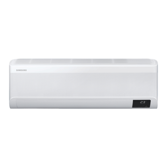
Unit Specifications and Features Indoor unit display NOTE: Different models have different front panel and display window. Not all the indicators describing below are available for the air conditioner you purchased. Please check the indoor display window of the unit you purchased. Illustrations in this manual are for explanatory purposes. -
Page 11: Operating Temperature
Operating temperature When your air conditioner is used outside of the following temperature ranges, certain safety protection features may activate and cause the unit to disable. Inverter Split Type FOR OUTDOOR UNITS COOL mode DRY mode WITH AUXILIARY 17°C - 32°C 10°C - 32°C ELECTRIC HEATER Room Temperature... -
Page 12: Other Features
Sleep Operation • Not all the functions are available for the air The SLEEP function is used to decrease conditioner, please check the indoor display energy use while you sleep (and don’t and remote control of the unit you purchased. need the same temperature settings to stay comfortable). -
Page 13: Setting Angle Of Airflow
Setting Angle of Air Flow • Setting vertical angle of air flow While the unit is on, use the SWING/DIRECT button on remote control to set the direction (vertical angle) of airflow. Please refer to the Remote Control Manual for details. NOTE ON LOUVER ANGLES When using COOL or DRY mode, do not set louver at too vertical an angle for long periods... -
Page 14: Care And Maintenance
Care and Maintenance Rinse the filter with fresh water, then shake Cleaning Your Indoor Unit off excess water. BEFORE CLEANING OR Dry it in a cool, dry place, and refrain from MAINTENANCE exposing it to direct sunlight. ALWAYS TURN OFF YOUR AIR CONDITIONER When dry, re-clip the air freshening filter to the larger filter, then slide it back into the SYSTEM AND DISCONNECT ITS POWER SUPPLY... - Page 15 Maintenance – CAUTION Pre-Season Inspection Before changing the filter or cleaning, • After long periods of non-use, or before periods turn off the unit and disconnect its power of frequent use, do the following: supply. When removing filter, do not touch metal •...
-
Page 16: Troubleshooting
Troubleshooting SAFETY PRECAUTIONS If ANY of the following conditions occurs, turn off your unit immediately! The power cord is damaged or abnormally warm • You smell a burning odor • The unit emits loud or abnormal sounds • A power fuse blows or the circuit breaker frequently trips •... - Page 17 Issue Possible Causes The outdoor unit The unit will make different sounds based on its current operating mode. makes noises Dust is emitted from The unit may accumulate dust during extended periods of non-use, which will be either the indoor or emitted when the unit is turned on.
- Page 18 Problem Possible Causes Solution Wait for the power to be restored Power failure The power is turned off Turn on the power The unit is not The fuse is burned out Replace the fuse working Replace batteries Remote control batteries are dead The Unit’s 3-minute protection Wait three minutes after restarting has been activated...
-
Page 19: Accessories
Accessories The air conditioning system comes with the following accessories. Use all of the installation parts and accessories to install the air conditioner. Improper installation may result in water leakage, electrical shock and fire, or cause the equipment to fail. The items are not included with the air conditioner must be purchased separately. -
Page 20: Installation Summary - Indoor Unit
Installation Summary - Indoor Unit 15cm (5.9in) 12cm 12cm (4.75in) (4.75in) 2.3m (90.55in) Attach Mounting Plate Select Installation Location Determine Wall Hole Position Drill Wall Hole Connect Piping Connect Wiring (not applicable for some locations in the US ) Wrap Piping and Cable Prepare Drain Hose (not applicable for some locations in the US ) STEP... -
Page 21: Unit Parts
Unit Parts NOTE: The installation must be performed in accordance with the requirement of local and national standards. The installation may be slightly different in different areas. Air-break switch (1) (2) Functional Filter (On Back of Remote Controller Wall Mounting Plate Main Filter - Some Units) Remote controller Holder Front Panel... -
Page 22: Indoor Unit Installation
Indoor Unit Installation NOTE ABOUT WALL HOLE: Installation Instructions – Indoor unit If there is no fixed refrigerant piping: PRIOR TO INSTALLATION While choosing a location, be aware that you Before installing the indoor unit, refer to the should leave ample room for a wall hole (see label on the product box to make sure that the Drill wall hole for connective piping step) model number of the indoor unit matches the... -
Page 23: Drill Wall Hole For Connective Piping
Step 3: Drill wall hole for connective piping 1. Determine the location of the wall hole based on the position of the mounting plate. Refer to Mounting Plate Dimensions. 2. Using a 65mm (2.5in) or 90mm(3.54in) Type B (depending on models )core drill, drill a hole in the wall. -
Page 24: Prepare Refrigerant Piping
Step 5: Connect drain hose Step 4: Prepare refrigerant piping By default, the drain hose is attached to the left- The refrigerant piping is inside an insulating hand side of unit (when you’re facing the back sleeve attached to the back of the unit. You of the unit). -
Page 25: Connect Signal Cable
WARNING BEFORE PERFORMING ANY ELECTRICAL WORK, READ THESE BEFORE PERFORMING ANY ELECTRICAL REGULATIONS OR WIRING WORK, TURN OFF THE MAIN POWER TO THE SYSTEM. 1. All wiring must comply with local and national electrical codes, regulations and must be Step 6: Connect signal cable installed by a licensed electrician. -
Page 26: Wrap Piping And Cables
pen front panel of the indoor unit. 1. O NOTE ABOUT WIRING Using a screwdriver, open the wire box cover THE WIRING CONNECTION PROCESS MAY on the right side of the unit. This will reveal DIFFER SLIGHTLY BETWEEN UNITS AND the terminal block. -
Page 27: Mount Indoor Unit
Step 8: Mount indoor unit Connect drain hose and refrigerant piping (refer to Refrigerant Piping Connection If you installed new connective piping to the section of this manual for instructions). outdoor unit, do the following: Keep pipe connection point exposed to If you have already passed the refrigerant perform the leak test (refer to Electrical piping through the hole in the wall, proceed... -
Page 28: Outdoor Unit Installation
Outdoor Unit Installation Install the unit by following local codes and install unit in the following locations: DO NOT regulations , there may be differ slightly between different regions. Near an obstacle that will block air inlets and outlets Near a public street, crowded areas, or where noise from the unit will disturb others Near animals or plants that will be harmed by hot air discharge... -
Page 29: Install Drain Joint
Step 2: Install drain joint(Heat pump unit only) Step 3: Anchor outdoor unit Before bolting the outdoor unit in place, you must The outdoor unit can be anchored to the install the drain joint at the bottom of the unit. ground or to a wall-mounted bracket with Note that there are two different types of drain bolt(M10). - Page 30 If you will install the unit on a wall-mounted If you will install the unit on the ground or bracket , do the following: on a concrete mounting platform, do the following: 1. Mark the positions for four expansion bolts CAUTION based on dimensions chart.
-
Page 31: Connect Signal And Power Cables
Step 4: Connect signal and power cables 2. Unscrew the electrical wiring cover and remove it. The outside unit’s terminal block is protected by 3. Unscrew the cable clamp below the terminal an electrical wiring cover on the side of the unit. block and place it to the side. -
Page 32: Refrigerant Piping Connection
Refrigerant Piping Connection When connecting refrigerant piping, do not let substances or gases other than the specified refrigerant enter the unit. The presence of other gases or substances will lower the unit’s capacity, and can cause abnormally high pressure in the refrigeration cycle. This can cause explosion and injury. -
Page 33: Remove Burrs
Step 2: Remove burrs PIPING EXTENSION BEYOND FLARE FORM Burrs can affect the air-tight seal of refrigerant Outer Diameter of A (mm) piping connection. They must be completely Max. Pipe (mm) Min. Max. removed. Ø 6.35 (Ø 0.25”) 0.7 (0.0275”) 1.3 (0.05”) Hold the pipe at a downward angle to prevent Ø... - Page 34 Tighten the flare nut as tightly as possible by hand. Using a spanner, grip the nut on the unit tubing. While firmly gripping the nut on the unit tubing, use a torque wrench to tighten the flare nut according to the torque values in the Torque Requirements table below.
-
Page 35: Air Evacuation
Air Evacuation If there is a change in system pressure, refer Preparations and Precautions to Gas Leak Check section for information Air and foreign matter in the refrigerant circuit can on how to check for leaks. If there is no cause abnormal rises in pressure, which can damage change in system pressure, unscrew the cap from the packed valve (high pressure valve). -
Page 36: Note On Adding Refrigerant
Note on Adding Refrigerant Some systems require additional charging depending on pipe lengths. The refrigerant should be charged from the service port on the outdoor unit’s low pressure valve. The additional refrigerant to be charged can be calculated using the following formula: ADDITIONAL REFRIGERANT PER PIPE LENGTH Connective Pipe Air Purging... -
Page 37: Electrical And Gas Leak Checks
Electrical and Gas Leak Checks Before Test Run WARNING – RISK OF ELECTRIC SHOCK Only perform test run after you have completed ALL WIRING MUST COMPLY WITH LOCAL the following steps: AND NATIONAL ELECTRICAL CODES, Electrical Safety Checks – Confirm that •... -
Page 38: Test Run
Test Run DOUBLE-CHECK PIPE CONNECTIONS Test Run Instructions During operation, the pressure of the You should perform the Test Run for at least 30 refrigerant circuit will increase. This may minutes. reveal leaks that were not present during your Connect power to the unit. initial leak check. -
Page 39: In Using
• The local gas regulations shall be observed. recommended by Samsung. • To handle, purge, and dispose the refrigerant, or • Do not pierce or burn. break into the refrigerant circuit, the worker should • Be aware that refrigerants may not contain an... - Page 40 • Because the working pressure for R-32 is 1.6 times Installation of the outdoor unit higher than that for R-22, use exclusive pipings and tools specified. In case of replacing an R-22 • While in installation or relocation of the product, do model with an R-32 model, be sure to replace the not mix the refrigerant with other gases including conventional pipings and flare nuts with exclusive...
- Page 41 • Replace components only with parts specified by • The recovery system shall operate normally Samsung. Other parts may result in the ignition of according to the specified instructions and shall be refrigerant in the atmosphere from a leak.
- Page 42 Maintenance Procedures Performing the gas leak tests for repair • Before starting the process, power supply must be available. In case of repair of the refrigerant circuit, the 1 Be familiar with the equipment details. following procedure must be kept to consider flammability.
- Page 47 Displayed when ECO feature is activated.
- Page 56 QUESTIONS OR COMMENTS? COUNTRY CALL OR VISIT US ONLINE AT 1800 40 SAMSUNG (1800 40 7267864) (Toll-Free) INDIA www.samsung.com/in/support 1800 5 SAMSUNG (1800 5 7267864) (Toll-Free) This product is RoHS compliant This appliance is filled with R-32.
Need help?
Do you have a question about the AR Series and is the answer not in the manual?
Questions and answers