
Related Manuals for IBASE Technology ET977


Summary of Contents for IBASE Technology ET977
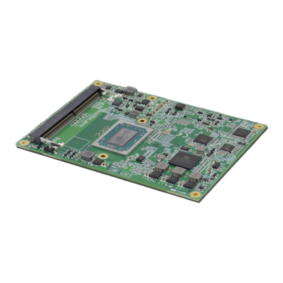
- Page 1 ET977 AMD Ryzen™ Embedded V1000/R1000 COM Express Type 6 Module User’s Manual Version 1.0...
- Page 2 No part of this publication may be reproduced, copied, stored in a retrieval system, translated into any language or transmitted in any form or by any means, electronic, mechanical, photocopying, or otherwise, without the prior written consent of IBASE Technology, Inc. (hereinafter referred to as “IBASE”). Disclaimer IBASE reserves the right to make changes and improvements to the products described in this document without prior notice.
- Page 3 0.1% by weight (1000 ppm) except for cadmium, limited to 0.01% by weight (100 ppm). • Lead (Pb) • Mercury (Hg) • Cadmium (Cd) • Hexavalent chromium (Cr6+) • Polybrominated biphenyls (PBB) • Polybrominated diphenyl ether (PBDE) ET977 Series User’s Manual...
- Page 4 Danger of explosion if the internal lithium-ion battery is replaced by an incorrect type. Replace only with the same or equivalent type recommended by the manufacturer. Dispose of used batteries according to the manufacturer’s instructions or recycle them at a local recycling facility or battery collection point. ET977 Series User’s Manual...
- Page 5 Software in use (such as OS and application software, including the version numbers) If repair service is required, you can download the RMA form at http://www.ibase.com.tw/english/Supports/RMAService/. Fill out the form and contact your distributor or sales representative. ET977 Series User’s Manual...
-
Page 6: Table Of Contents
Block Diagram ..................5 Board Layout ..................6 Dimensions ..................7 Chapter 2 Hardware Configuration .......... 9 ET977 COM Express Connectors ............11 Chapter 3 Drivers Installation ..........15 Introduction ..................16 AMD Ryzen™ V1000 Graphics Drivers ..........16 Realtek HD Audio Driver Installation ..........19 LAN Driver Installation ............... - Page 7 This page is intentionally left blank. ET977 Series User’s Manual...
-
Page 9: Chapter 1 General Information
Chapter 1 General Information The information provided in this chapter includes: • Features • Packing List • Optional Accessories • Specifications • Block Diagram • Board Layout • Board Dimensions... -
Page 10: Introduction
Standard features supported with interface on the carrier board include an Intel® I210IT Gigabit controller, 4x USB 3.1 ports, 8x USB2.0 ports, and 2x SATA 3.0 ports. ET977 measures 125mm x 95mm and supports the Windows 10 (64bit) OS, with an operating temperature range of 0°C to 60°C. -
Page 11: Packing List
General Information Packing List Your ET977 package should include the items listed below. If any of the items below is missing, contact the distributor or dealer from whom you purchased the product. • ET977 COM Express Module • Disk (including drivers and flash memory utility) •... - Page 12 TPM 2.0 Infineon SLB9670VQ2 Certification CE (EN55032:2012), FCC Class B OS support Windows 10 (64bit) Board size 125mm x 95mm RoHS 2 Operating 0°C~60°C temperature Storage -20°C~80°C temperature All specifications are subject to change without prior notice. ET977 Series User’s Manual...
-
Page 13: Block Diagram
General Information Block Diagram ET977 Series User’s Manual... -
Page 14: Board Layout
Board Layout Top View Bottom View *The pictures above are for reference only. ET977 Series User’s Manual... -
Page 15: Dimensions
General Information Dimensions Unit: mm ET977 Series User’s Manual... - Page 16 This page is intentionally left blank. ET977 Series User’s Manual...
-
Page 17: Chapter 2 Hardware Configuration
Chapter 2 Hardware Configuration This section provides information on jumper settings and connectors on the board in order to set up a workable system. The topics covered are: • Memory Installation • Connector locations and information... - Page 18 Gently push the module in an upright position until the clips of the slot close to hold the module in place when the module touches the bottom of the slot. To remove the module, press the clips outwards with both hands, and the module will pop-up. ET977 Series User’s Manual...
-
Page 19: Et977 Com Express Connectors
Hardware Configuration ET977 COM Express Connectors COM Express Module Type 6 Connector (COM_E_AB1, COM_E_CD1) Row A Row B Row C Row D Signal Signal Signal Signal GND (FIXED) GND (FIXED) GND (FIXED) GND (FIXED) GBE0_MDI3- GBE0_ACT# GBE0_MDI3+ LPC_FRAME# USB_SSRX0- USB_SSTX0-... - Page 20 D69 PEG_TX5- (R1000 NC) (R1000 NC) A70 GND (FIXED) GND (FIXED) C70 GND (FIXED) D70 GND (FIXED) LVDS_A0+/ LVDS_B0+ C71 PEG_RX6+ D71 PEG_TX6+ (R1000 NC) (R1000 NC) eDP_TX2+ Row A Row B Row C Row D ET977 Series User’s Manual...
- Page 21 A107 VCC_12V B107 VCC_12V C107 VCC_12V D107 VCC_12V A108 VCC_12V B108 VCC_12V C108 VCC_12V D108 VCC_12V A109 VCC_12V B109 VCC_12V C109 VCC_12V D109 VCC_12V A110 GND (FIXED) B110 GND (FIXED) C110 GND (FIXED) D110 GND (FIXED) ET977 Series User’s Manual...
- Page 22 DDR4 SO-DIMM Slot & ATX/AT Switch Function Connector Name DDR4 SO-DIMM Slot J1, J3 ATX/AT Switch ET977 Series User’s Manual...
-
Page 23: Chapter 3 Drivers Installation
Chapter 3 Drivers Installation This chapter introduces installation of the following drivers: • AMD Ryzen™ V1000/R1000 Graphics Drivers • Realtek HD Audio Driver Installation • LAN Driver Installation • Observer Setup Wizard... -
Page 24: Introduction
Introduction This section describes the installation procedures for software and drivers. AMD Ryzen™ V1000/R1000 Graphics Drivers Insert the driver CD/DVD into the corresponding drive. Click AMD Ryzen V1000 Drivers and then AMD Ryzen V1000/R1000 Graphics Drivers. ET977 Series User’s Manual... - Page 25 Driver Installation Read the software license agreement and click Accept and Install to proceed. Choose and click on either Express Install or Custom Install. ET977 Series User’s Manual...
- Page 26 After the installation, restart the computer when prompted for changes to take effect. ET977 Series User’s Manual...
-
Page 27: Realtek Hd Audio Driver Installation
Driver Installation Realtek HD Audio Driver Installation Click AMD on the left pane and then AMD Ryzen V1000/R1000 Drivers. Click Realtek High Definition Audio Driver. ET977 Series User’s Manual... - Page 28 On the Welcome screen of the InstallShield Wizard, click Yes to continue with the installation. When installation is complete, restart the computer when prompted. ET977 Series User’s Manual...
-
Page 29: Lan Driver Installation
Click LAN Card on the left pane and then Intel LAN Controller Drivers. Click Intel(R) I21x Gigabit Networks Drivers. When the Welcome screen to the install wizard appears, click Next. On the following screen, accept the license agreement and click Next. ET977 Series User’s Manual... - Page 30 On the Setup Options screen, tick the checkbox to select the desired driver(s) for installation. Then click Next to continue. Click Install to begin the installation. Once “Install wizard is Completed,” click Finish. ET977 Series User’s Manual...
-
Page 31: Observer Setup Wizard
Driver Installation Observer Setup Wizard Click Tools on the left pane and then Observer. On the Welcome screen, click Next to install Observer on your system. It is recommended that you close all other applicatoins before continuing. ET977 Series User’s Manual... - Page 32 To continue, click Next. If you would like to select a different folder, click Browse. In the Ready to Install screen, click Install to continue. To complete the installation, restart the computer when prompted. Click Finish. ET977 Series User’s Manual...
-
Page 33: Chapter 4 Bios Setup
Chapter 4 BIOS Setup This chapter describes the different settings available in the AMI BIOS that comes with the board. The topics covered in this chapter are as follows: • Main Settings • Advanced Settings • Chipset Settings • Security Settings •... -
Page 34: Introduction
These defaults have been carefully chosen by both AMI and your system manufacturer to provide the absolute maximum performance and reliability. Changing the defaults could make the system unstable and crash in some cases. ET977 Series User’s Manual... -
Page 35: Main Settings
Set the time. Use the <Tab> key to switch System Time between the data elements. 4.4 Advanced Settings This section allows you to configure, improve your system and allows you to set up some system features according to your preference. ET977 Series User’s Manual... - Page 36 O.S. will not show Security Device. TCG EFI protocol Support and INT1A interface will not be available. Schedule an operation for the Security Device. NOTE: Pending Your computer will reboot during restart in order to operation change State of Security Device. ET977 Series User’s Manual...
- Page 37 Enables / Disables the system ability to Enable Hibernation hibernate (OS/S4 Sleep State). This option may be not effective with some OS. Selects an ACPI sleep state where the system ACPI Sleep State will enter when the Suspend button is pressed. ET977 Series User’s Manual...
- Page 38 4.4.3 IDE Configuration BIOS Setting Description SATA Ports Detects the connection of SATA Port0 and SATA Port1. 4.4.4 eDP/LVDS Configuration ET977 Series User’s Manual...
- Page 39 BIOS Setup BIOS Setting Description eDP / LVDS Control Enable or Disables eDP / LVDS out. ET977 Series User’s Manual...
- Page 40 4.4.5 F81964 Super IO Configuration ET977 Series User’s Manual...
- Page 41 BIOS Setup ET977 Series User’s Manual...
- Page 42 4.4.6 F81804SEC Super IO Configuration ET977 Series User’s Manual...
- Page 43 Sets the temperature whereby the CPU smart fan is Control enabled. These fields are the parameters of the hardware Temperatures / monitoring function feature of the motherboard. The Voltages values are read-only values as monitored by the system and show the PC health status. ET977 Series User’s Manual...
- Page 44 4.4.8 CPU Configuration BIOS Setting Description Node 0 Information Displays the memory information related to Node 0. ET977 Series User’s Manual...
- Page 45 BIOS Setup 4.4.9 AMI Graphic Output Protocol Policy BIOS Setting Description Output Select Allows you to select an output interface. ET977 Series User’s Manual...
- Page 46 Host Controller. Device power-up Auto uses default value for a Root port it is delay 100ms. But for a Hub port, the delay is taken from Hub descriptor. Options: Auto / Manual ET977 Series User’s Manual...
- Page 47 BIOS Setup 4.4.11 CSM Configuration BIOS Setting Description CSM Support Enables / Disables CSM support. Controls the execution of UEFI and Legacy PXE OpROM. Network Options: Do not launch / Legacy ET977 Series User’s Manual...
- Page 48 4.4.12 Network Stack Configuration BIOS Setting Description Network Stack Enables / Disables UEFI Network Stack. ET977 Series User’s Manual...
- Page 49 BIOS Setup 4.4.13 AMD CBS ET977 Series User’s Manual...
-
Page 50: Chipset Settings
4.5.1 SB USB Configuration BIOS Setting Description SB USB Configuration Options for SB USB Configuration. 4.5.1.1. XHCI Ports BIOS Setting Description XHCI 0 & XHCI 1 Enables / Disables the XHCI0 & XHCI1 ports Ports (XHCI/EMCI). ET977 Series User’s Manual... -
Page 51: Security Settings
BIOS Setup 4.6 Security Settings BIOS Setting Description Administrator Sets an administrator password for the setup Password utility. User Password Sets a user password. Secure Boot Customizable Secure Boot ET977 Series User’s Manual... - Page 52 Platform Key(PK) is enrooled, System mode is user/deployed, and CSM is disabled Customizable Secure Boot mode: Secure Boot In Custom mode, Secure Boot Policy Variables Customization can be configured by a physically present user without full authentication. ET977 Series User’s Manual...
-
Page 53: Boot Settings
Boot mode select Selects a Boot mode, Legacy / UEFI. Boot Option Priorities Sets the system boot order. UEFI Hard Disk Drive Specifies the Boot Device Priority sequence BBS Priorities from available UEFI Hard Disk Drivers. ET977 Series User’s Manual... -
Page 54: Save & Exit
Save the changes done so far as User Defaults. Restore User Defaults Restore the user defaults to all the setup options. Launch EFI Shell from Attempts to launch EFI Shell application filesystem device (Shell.efi) from one of the available filesystem devices ET977 Series User’s Manual... -
Page 55: Appendix
Appendix This section provides the mapping addresses of peripheral devices and the sample code of watchdog timer configuration. -
Page 56: I/O Port Address Map
PCI Express Root Complex 0x00000D00-0x0000FFFF PCI Express Root Complex 0x0000F000-0x0000FFFF PCI Express Root Port 0x0000E000-0x0000EFFF PCI Express Root Port 0x0000E000-0x0000EFFF PCI Express Upstream Switch Port PCI Express Downstream Switch 0x0000E000-0x0000EFFF Port 0x00000040-0x00000043 System timer 0x00000010-0x0000001F Motherboard resources ET977 Series User’s Manual... - Page 57 0x00000C6C-0x00000C6C Motherboard resources 0x00000C6F-0x00000C6F Motherboard resources 0x00000CD0-0x00000CD1 Motherboard resources 0x00000CD2-0x00000CD3 Motherboard resources 0x00000CD4-0x00000CD5 Motherboard resources 0x00000CD6-0x00000CD7 Motherboard resources 0x00000CD8-0x00000CDF Motherboard resources 0x00000800-0x0000089F Motherboard resources 0x00000B00-0x00000B0F Motherboard resources 0x00000B20-0x00000B3F Motherboard resources 0x00000900-0x0000090F Motherboard resources 0x00000910-0x0000091F Motherboard resources ET977 Series User’s Manual...
- Page 58 PCI Express Root Complex 0x000003B0-0x000003DF PCI Express Root Complex 0x00000D00-0x0000FFFF PCI Express Root Complex 0x0000F000-0x0000FFFF PCI Express Root Port 0x0000E000-0x0000EFFF PCI Express Root Port 0x0000E000-0x0000EFFF PCI Express Upstream Switch Port PCI Express Downstream Switch 0x0000E000-0x0000EFFF Port ET977 Series User’s Manual...
-
Page 59: Interrupt Request Lines (Irq)
PCI Express Downstream Switch Port IRQ 4294967253~55 AMD Radeon(TM) Vega 11 Graphics IRQ 4294967268~ AMD USB 3.10 eXtensible Host Controller - 4294967283 1.10 (Microsoft) IRQ 4294967288 PCI Express Downstream Switch Port IRQ 4294967284~ AMD PSP 10.0 Device 4294967285 ET977 Series User’s Manual... -
Page 60: Watchdog Timer Configuration
F81804 WDT Main Function Example INTN EFIAPI ShellAppMain ( IN UINTN Argc, IN CHAR16 **Argv int time = 10; //seconds if(!F81804Init()){ //Check if this SIO is F81804 return 0; F81804WdtEnable(time); //F81804WdtDisable(); ET977 Series User’s Manual... - Page 61 //Check if this SIO is F81804 return 0; F81804DioInit(); //Init F81804 DIO F81804SetOutput(0x00); //Set out0-3 to Low DIO = F81804GetInput(); if(DIO != 0x00){ return 0; F81804SetOutput(0x1E); //Set out0-3 to High DIO = F81804GetInput(); if(DIO != 0x0F){ return 0; ET977 Series User’s Manual...
- Page 62 ((tmp2 & 0x80) >> 4); return input; //Check if CHIP_ID for F81804 UINT8 F81804Init(){ UINT8 CHIP_ID1, CHIP_ID2; IoWrite8(F81804_CONFIG_INDEX, 0x20); CHIP_ID1 = IoRead8(F81804_CONFIG_DATA); IoWrite8(F81804_CONFIG_INDEX, 0x21); CHIP_ID2 = IoRead8(F81804_CONFIG_DATA); if((CHIP_ID1 != 0x15) && (CHIP_ID2 != 0x02)) return 0; ET977 Series User’s Manual...
- Page 63 F8104ProgramRegister(0x98, 0xE1, 0x1E); VOID F8104ProgramRegister( UINT8 Register, UINT8 AndData, UINT8 OrData){ UINT8 temp; IoWrite8(F81804_CONFIG_INDEX, Register); temp = IoRead8(F81804_CONFIG_DATA); temp &= AndData; temp |= OrData; IoWrite8(F81804_CONFIG_DATA, temp); VOID F8104EnterConfig(){ IoWrite8(F81804_CONFIG_INDEX, F81804_CONFIG_MODE_ENTER_VALUE); IoWrite8(F81804_CONFIG_INDEX, F81804_CONFIG_MODE_ENTER_VALUE); VOID F8104ExitConfig(){ IoWrite8(F81804_CONFIG_INDEX, F81804_CONFIG_MODE_EXIT_VALUE); ET977 Series User’s Manual...
- Page 64 F8104ProgramRegister(0x27, ~(BIT3|BIT2|BIT0), BIT3); F8104ProgramRegister(0x2A, ~(BIT4|BIT5|BIT6), (BIT5|BIT6)); F8104ProgramRegister(0x07, 0x00, 0x07); F8104ProgramRegister(0x30, 0x00, 0x01); F8104ProgramRegister(0xF5, 0xF0, 0x52); //count mode is second F8104ProgramRegister(0xF6, 0x00, time); //set timer time seconds F8104ProgramRegister(0xFA, 0xFE, 0x01); //enable WDTO output F8104ProgramRegister(0xF5, 0xFF, 0x20); //start counting F8104ExitConfig(); ET977 Series User’s Manual...
Need help?
Do you have a question about the ET977 and is the answer not in the manual?
Questions and answers