
Related Manuals for Extreme Flight RC EXTRA 300 EXP V2


Summary of Contents for Extreme Flight RC EXTRA 300 EXP V2
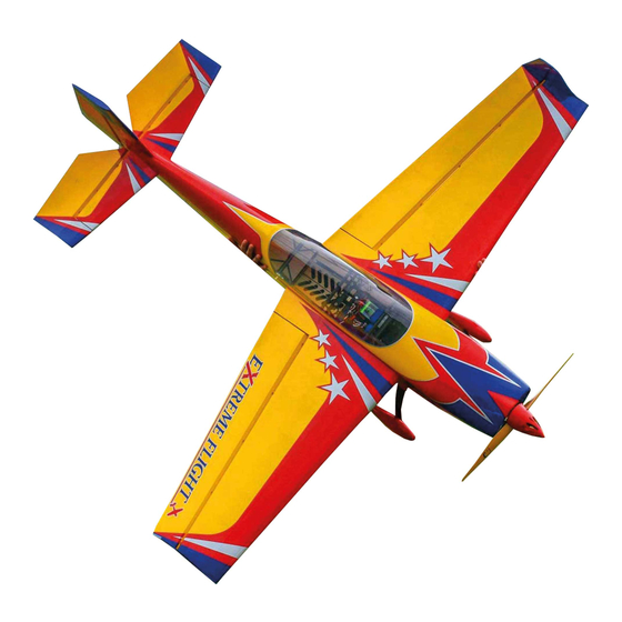
- Page 1 70" EXTRA 300 EXP Assembly Manual Copyright 2019 Extreme Flight RC www.modellmarkt24.ch; www.modellmarkt24.ch; www.modellmarkt24.de www.modellmarkt24.de...
- Page 2 THIS IS NOT A TOY! Serious injury, destruction of property, or even death may result from the misuse of this product. Extreme Flight RC is providing you, the consumer with a very high quality model aircraft component kit, from which you, the consumer, will assemble a flying model.
- Page 3 A few tips to ensure success 1. We are very pleased with the level of craftsmanship displayed by the builders in our factory. Through hundreds of grueling test flights containing maneuvers that no aircraft should be subjected to, our prototypes have remained rigid and completely airworthy.
- Page 4 30cc aircraft. As such the 70" Extra 300 EXP V2 now shares the ultra lightweight and rugged laminated composite construction of our other current airframes and the 2 mini servos previously used for elevator actuation on the V1 version have been replaced with a single high torque standard size metal gear servo.
- Page 5 Elevator-please note the elevator/stab assembly on the V2 version of the Extra is now a single piece unit that is permanently glued to the airframe and uses a single servo for elevator actuation. 1. Locate the horizontal stabilizer/elevator assembly as well as the composite control horns and base plates from the elevator hardware package.
- Page 6 3. Remove the horn assembly and use your #11 blade to remove the covering from inside the ink line you traced around the control horn base. Wipe away the ink line with a paper towel soaked in denatured alcohol. Scuff the portion of the horns that will be inserted into the elevator with sandpaper.
- Page 7 www.modellmarkt24.ch; www.modellmarkt24.ch; www.modellmarkt24.de www.modellmarkt24.de...
- Page 8 www.modellmarkt24.ch; www.modellmarkt24.ch; www.modellmarkt24.de www.modellmarkt24.de...
- Page 9 4. In this step I will outline the procedure we use to install the hinges. I have found it best to hinge the elevator/stab before gluing it into position in the fuselage. There are several methods to hinge a model and several adhesives you can use. We will describe the way we do it, as this method has proven itself over many years of model building.
-
Page 10: Wing Assembly
Wing Assembly 6. The assembly process for the wing is almost identical to that of the stab/elevator. For this reason we will not go into quite as much detail as in the previous procedure. Remove the aileron from the wing panel. Locate the 2 slots for the control horns and remove the covering from the slots with a sharp #11 blade. - Page 11 7. Locate the aileron servo mount and remove the covering from this area. Use a sealing iron to seal the edges of the covering to the sides of the servo opening. Take a few minutes to apply some CA to the joints of the servo rails and the ribs. 8.
- Page 12 9. Before beginning the next assembly process, take a few minutes with your sealing iron on a medium heat setting and go over all seams, paying special attention to thin trim stripes and the seam at the leading edge of the wing. If there are wrinkles in the covering on the leading edge sheeting use a heat gun with a microfiber cloth to remove them and prevent digging into the wood with an iron.
- Page 13 10. Locate your assembled elevator assembly and the fuselage. Remove the covered block from the rear of the elevator slot and set it aside. Slide the elevator assembly into the slot in the rear of the fuselage and check for correct alignment. When satisfied remove the assembly and apply 30 minute epoxy to the center section of the elevator that will mate with the fuselage slot.
- Page 14 11. Once dry, glue the covered block into place with medium CA or epoxy. www.modellmarkt24.ch; www.modellmarkt24.ch; www.modellmarkt24.de www.modellmarkt24.de...
- Page 15 12. Locate the rudder, the rudder control horns and the 2 base plates. Use a sharp #11 blade to remove the covering from the 2 pre-cut slots in the rudder. Trial fit the 2 servo horns through the slots in the rudder and into their proper position. Measure to ensure they are centered and mark with a fine tipped felt pen to make it easy to reinstall properly when epoxy is applied.
- Page 16 www.modellmarkt24.ch; www.modellmarkt24.ch; www.modellmarkt24.de www.modellmarkt24.de...
- Page 17 13. Locate a 2mm ball link from the hardware bag. Drill a hole 2 inches back from the leading edge of the rudder on the bottom of the rudder surface to accept the shank on the ball link. 14. Scuff the shaft of the ball link with coarse sandpaper. Mix up a small amount of 5 minute epoxy and apply it to the ball link and the hole in the bottom of the rudder.
- Page 18 16. Next we'll install the landing gear. Locate the carbon fiber main landing gear, 4 3mm bolts, lock nuts and washers. Insert the gear into the slot on the bottom of the fuselage and center it in the slot. Secure the landing gear with 4 3mm bolts, washers and nylon insert lock nuts by inserting the bolts and washers into the pre-drilled holes in the aluminum gear mounts inside the fuselage with a long T-handle wrench.
- Page 19 18. Apply a thick bead of silicon glue or epoxy just below your pencil line all the way around the gear. Slide the fairing back into place and apply masking tape to keep it in position while the glue dries. 19.
- Page 20 20. While the Extra is still upside down let’s install the rudder and finish up the tailwheel installation. Apply 30 minute epoxy to the holes in the rudder post and to the rudder hinges. As you position the rudder onto the vertical fin, be sure the tailwheel tiller arm is inserted into the ball link.
- Page 21 21. Next let’s install the motor/engine. We have made this process very easy. If using the Xpwr 30 or DA-35 the positioning marks are already laser scribed on the firewall. Simply drill at the designated locations. If using another make or size of motor, the center and offset marks have been scribed into the front of the firewall with a laser.
- Page 22 Here are photos of our installation of a DLE-20cc engine on the Extra. Please note we used an aftermarket radial mount available here: http://www.seaplanesupply.com/aluminum.htm www.modellmarkt24.ch; www.modellmarkt24.ch; www.modellmarkt24.de www.modellmarkt24.de...
- Page 23 www.modellmarkt24.ch; www.modellmarkt24.ch; www.modellmarkt24.de www.modellmarkt24.de...
- Page 24 www.modellmarkt24.ch; www.modellmarkt24.ch; www.modellmarkt24.de www.modellmarkt24.de...
- Page 25 22. There are a pair of clear plastic airflow diverters to force incoming air over the Xpwr. We highly recommend installing these with Goop or epoxy to aid in the cooling of your motor. 23. Slide the cowl into position and secure with 2 3mm bolts inserted through the F1 former and into the blind nuts in the cowl.
- Page 26 24. Install your rudder servo in the provided location under the canopy using the supplied hardware with the output shaft toward the rear of the plane. 25. Next let’s install the pull-pull rudder cables. Look into the rear of the fuselage and you will see a nylon tube installed on each side of the fuselage.
- Page 27 www.modellmarkt24.ch; www.modellmarkt24.ch; www.modellmarkt24.de www.modellmarkt24.de...
- Page 28 27. Insert the bare end of the cable into the slot in the rear of the fuselage and feed it forward into the canopy area and make up the same type of linkage as you did previously. Electronically center your servo. Secure the linkage at both ends with a 3mm bolt and nylon insert lock nut.
- Page 29 28. Remove the covering over the hole in the rear of the fuselage for the elevator servo. We recommend the MKS 1220 metal gear digital servo for elevator actuation. Attach a 24" extension to the servo lead and install the servo with the output shaft toward the rear of the fuselage using the manufacturer supplied mounting hardware.
-
Page 30: Control Surface Throws
Again, this is just a starting point. Adjust to your liking. Thanks again for your purchase of the Extreme Flight RC 70 inch Extra 300EXP V2 ARF. I hope you enjoy assembling and flying yours as much as I have mine.
Need help?
Do you have a question about the EXTRA 300 EXP V2 and is the answer not in the manual?
Questions and answers