Advertisement
Quick Links
Advertisement

Subscribe to Our Youtube Channel
Related Manuals for Extreme Flight RC YAK-54


Summary of Contents for Extreme Flight RC YAK-54
- Page 1 68 INCH YAK-54 Instruction Manual...
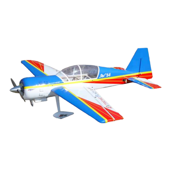
- Page 2 Thank you for your purchase of the Extreme Flight RC 68 inch Yak-54. Please take a few moments to read this instruction manual before beginning assembly. We have outlined a fast, clear and easy method to assemble this aircraft and familiarizing yourself with this process will aid in a quick, easy build.
- Page 3 F3A or Unlimited class IMAC schedules. The 3D performance of the Yak is unheard of in a plane this size. The 68” Yak-54 is truly unlimited in its performance capabilities.
- Page 4 ATTENTION! Due to a communication error, there are some extra hardware components included with this aircraft. In addition to the Du-bro hardware package located next to the cowl, you will find a second hardware package in the cardboard divider containing the composite landing gear. You may choose to discard this metric hardware, but there are five components in this hardware package that are essential to the assembly of this aircraft.
-
Page 5: Wing Assembly
WING ASSEMBLY 1. We will begin by hinging the aileron to the wing. There are 7 CA hinges that will be installed per wing/aileron. Use a ruler and measure from the root (closest to fuselage) of the aileron to the tip and locate the hinge slots, then slit the covering to access the slot (already cut) for the hinge. - Page 6 Figure 2 3. Locate the servo bay (bottom of wing near center) under the covering by feel, once located cut the covering to expose the opening. You will need a 6” or 12” wire extension hooked to your servo lead so it will be able to go inside the fuselage once the wings are installed to reach the receiver.
- Page 7 4. Secure your servo in the wing’s mounts with the output shaft closest to the hinge line. Measure on the bottom side, at the root of the aileron 11 ½”, you will feel a small hole under the covering where the 6-32 control horn bolt will be located, remove the covering from this hole.
-
Page 8: Fuselage Assmebly
without epoxy protruded from the wing, allow to dry. Take the included ¼” X 20 plastic wing bolts and cut them to ¾” long from the bottom of the washer head. Refer to figure 5, it will show how the wing root will look when completed. From left to right you will see the first alignment pin, then the carbon fiber wing tube location, followed by the wing bolt, then the aileron wire and finally the rear alignment pin. - Page 9 Figure 6 Figure 7 7. Trim the covering around the wing slot, elevator servos and horizontal stabilizer locations. EF suggests that you leave 1/8” of covering at the wing slot (see figure 8) and iron that into the slot. At the horizontal, leave 1/16” of covering and iron into the slot.
- Page 10 Figure 9 9. We will now prepare to mount the horizontal into the fuselage. First locate the exact center of the horizontal, next take the measurements of the front and back widths of the stabilizer slot in the fuselage and transfer those to the horizontal.
- Page 11 In this picture I have located the center and cut the covering away but, have left 1/16” extra to keep bare balsa from showing. At this point the horizontal should be ready to install. Figure 10 I have now installed the horizontal with 30 minute epoxy and wiped the excess away.
- Page 12 I now tip the plane onto its nose and view it from behind to be sure I am parallel with the wing. In figure 11 you will notice the tail is propped up onto a box to make it level. You may use that method to view it from the front and back to be sure the...
- Page 13 12. Take the rudder and locate the hinge slots in the same manner that we did the ailerons. The following are the measurements for the hinge locations, measure from the bottom upwards on the rudder. (There are four slots. 1. 1 ½” 2.
- Page 14 This is the hole for the 6-32 control horn. This will be later in the assembly process. Elevator control horn location. The small groove may be cut here. Here is the tail wheel assembly. Figure 15 13. Now lets install the elevator servo. Attach a 12 – 18” extension to the servo and fit into either bay to begin.
- Page 15 TIP: You may run your servo wires thru the fuselage formers to the receiver. This will aid to keep them secured during flight. 14. The rudder runs on a pull pull set up that is very easy to install. Lets begin by mounting the servo in the rails just under the canopy.
- Page 16 NOTE: In figure 17 the heat shrink has not been slid onto the crimp and rigging coupler and has not been shrunk. This shows it before shrinking. Cupped washer Cone nut Hex nut Clear control horn Figure 18 15. In this step we will mount a YS 110 engine, although other motors would work EF feels the best performance will be attained with this engine choice.
- Page 17 This vertical centerline is 2 5/32” from the side. This horizontal centerline is 2 1/32”from the top. This mark is 9/32” from the vertical centerline and should be used to center engine. The right engine mount is 1” from the right side. Figure 19 17.
- Page 18 Figure 20 20. Locate the cowl, 4 #4 bonded sealing washers and socket head mounting screws. The YS 110 will stick thru the bottom of the cowl so you will need to trim as desired. (EF also recommends cutting out the bottom portion only of the oil cooler located on the very bottom of the cowl for proper cooling.) The cowl needs to go onto the fuselage until it is 1/8”...
- Page 19 Figure 21 21. Locate the tire/wheel pant hardware package. Begin by inserting the 6-32 X 1 ½” bolt thru one tire, followed by a #6 nylon washer and nylon insert nut (locknut), tighten the nut but leave it loose enough that the tire spins freely. Drill a 9/64”...
- Page 20 4-40 blind nut Slot that fits over locknut Figure 23 6-32 locknut Slot fits over locknut Figure 24 22. Assemble the fuel tank according to instructions and mount it onto the tray in front of the wing tube. It can be secured with Velcro or nylon cable ties. 23.
- Page 21 used. There are several areas this servo can be installed, however you may need to install hardwood to accommodate some areas. Figure 25 shows a mini servo installed in a hardwood stick mount just aft of the wing tube. Figure 25 24.
- Page 22 There are a total of 4 of these holes. Insert the 4-40 bolt/washer into each of these to secure the hatch for flight. Figure 27 25. Mount your switch, battery and receiver in the fuselage, try to place the receiver and battery pack to attain proper center of gravity ( CG range is from the front of the wing tube to one half inch behind the wing tube).
- Page 23 This shows the inside of the switch mount. You will need to remove some foam to accommodate most switches. Figure 29 This shows the final radio layout inside the fuselage. The battery rests under the fuel tank tray. The receiver has been velcro’d to the lower fuselage former.
- Page 24 Take your time and devote the first several flights to properly trimming your aircraft and you will be rewarded with an incredible flying machine. Thanks again for your purchase of the Extreme Flight RC 68” Yak-54. See you at the flying field!
Need help?
Do you have a question about the YAK-54 and is the answer not in the manual?
Questions and answers