Table of Contents
Advertisement
Quick Links
®
NATURAL GAS (G20, G25 & G25.3), PROPANE GAS (G31)
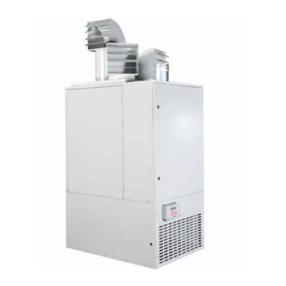
PVE GAS FIRED FLOOR STANDING HEATER
INSTALLATION/ COMMISSIONING/SERVICING
EU)2016/426(GAR),2009/125/EC(ErP), 2014/35/EU(LVD),and2014/30/EU(EMC)
Regulations and Directives.
The following harmonised standards have been applied:
EN 1020, EN 60335-1, EN 60335-2-102, EN 55014-1, and EN 55014-2
Please read this document carefully before commencing installation, commissioning and/or servicing.
Leave it with the end user/site agent to be placed in their premises technical file after installation.
WARNING
Improper installation, adjustment, alteration, service or maintenance can cause property damage, injury or death.
All work must be carried out by appropriately qualified persons.
The manufacturer does not take any responsibility in the event of non-observance of the regulations concerning the connection of the apparatus causing
a dangerous operation possibly resulting in damage to the apparatus and/or environment in which the unit is installed.
Manual Part No. D301113 Issue C
Advertisement
Table of Contents

Related Manuals for Nortek REZNOR PVE Series


Summary of Contents for Nortek REZNOR PVE Series
- Page 1 ® NATURAL GAS (G20, G25 & G25.3), PROPANE GAS (G31) PVE GAS FIRED FLOOR STANDING HEATER INSTALLATION/ COMMISSIONING/SERVICING EU)2016/426(GAR),2009/125/EC(ErP), 2014/35/EU(LVD),and2014/30/EU(EMC) Regulations and Directives. The following harmonised standards have been applied: EN 1020, EN 60335-1, EN 60335-2-102, EN 55014-1, and EN 55014-2 Please read this document carefully before commencing installation, commissioning and/or servicing.
-
Page 3: Table Of Contents
Contents Contents ..........................1 General health and safety ......................2 Gas leak emergency ......................... 2 Warranty ..........................3 Location/Positioning ........................3 General ............................ 3 Compliance notices ........................5 General product information ..................... 6 Heater model examples ......................6 Heater dimensions ........................7 Technical data .......................... -
Page 4: General Health And Safety
General health and safety WARNING • Do not store or use petrol or other Warning is used when failure flammable vapours and liquids in the to heed or implement the vicinity of the appliance. instruction(s) can lead to not only •... -
Page 5: Warranty
Location/Positioning In addition the installation must be carried out in accordance with national or local Under no circumstances should regulations and any other relevant Codes any item be placed on or above of Practice by a qualified installer. Isolate all any part of the heater, whether it electrical supplies to the heater &... - Page 6 This appliance has been manufactured The services that are to be connected (fuel specifically for room heating and must be used pipes, power supply, etc.) must be suitably for this purpose. Contractual liability of the secured and must not be dangerous with the manufacturer in respect of damages caused risk of tripping.
-
Page 7: Compliance Notices
• Ferrous materials In addition, operators must be suitably trained in the use of the appliance so as to ensure its • Aluminium and copper continued safe and efficient use. • Electrical wiring The manufacturer has a commitment to continuous improvement and therefore reserve •... -
Page 8: General Product Information
Flue/Combustion Air Spigot If the country code and gas category on the appliance data label does not match the Each heater is fitted with two spigots both country of installation or the country codes of which are located on top of the appliance. and gas category’s as shown in this instruction One of the pair is for connection for the flue manual, it will be necessary to contact the... -
Page 9: Heater Dimensions
Heater dimensions Figure 2b Unit side view PVED Figure 2a Unit front view PVED PVE 30 - 50 PVE 72 PVE 95 -145 Figure 2c Top view PVED Model Overall height PVED 1810 1810 1890 1990 2041 2040 Unit height 1625 1625 1705... - Page 10 Nozzles (Optional Extra) Figure 3a : PVEN 30 - 50 Figure 3c : PVEN 95 Figure 3b : PVEN 72 Figure 3d : PVEN 120 Figure 3e : PVEN 145 Figure 4 Nozzle louvres Units with more than two nozzles are to be supplied as standard with height extensions for rear nozzles.
- Page 11 Figure 5a : PVEN 30 - 50 Figure 5b : PVEN 72 - 120 Figure 5c : PVEN 145 Model Overall height with nozzles 1991 1991 2101 2201 2301 2301 Nozzles Table 4 : Overall height when fitted with standard nozzles Prior to installation the following points are to be considered.
-
Page 12: Technical Data
Technical data Gas type Model Heat output (G20) 35.2 49.3 73.4 95.4 128.5 136.7 Heat input nett (G20) 37.7 52.8 79.3 104.5 140.0 150.0 Efficiency nett 93.4 93.3 92.6 91.3 91.8 91.2 Efficiency low nett 91.7 90.3 89.7 88.5 89.9 89.4 Heat output low fire 20.7... -
Page 13: Electrical Supply
Country code Approved gas category I2Esi I2E(R)B AT,CH,CZ,DK,EE,ES,FI,GB,GR,IE,IT,BGIS,LT, LV,NO,PT,RO,SE,SI,SK,TR,CY,HR PL,LU,DE,RO I2ELL I2Ek BE,CZ,FR,IE,IT,ES,CH,GB, I3P (37) SI,LU, SK,PT,PL,TR,GR,HR I3P (30) Table 6 : Approved gas categories Model Restriction Flue diameter Supply voltage 1*230V N Power absorption 1.25 1.90 1.85 2.90 3.10 3.40 Gross flue temperature °C... -
Page 14: Pre Installation
case of a unit wired for a three phase supply, Prior to installation, the assembly of the heater the supply should only be used to serve the should be completed, it is advisable that this is heater itself and no other plant or equipment. undertaken in the area where the heater is to The position of the isolation switch must be be sited obey the clearances in table 3 . -
Page 15: Warm Air Circulation
PVE free blowing heaters are at their most maintained, thereby offering the best heat effective when located as close to the working distribution. area as possible. However care should be exercised to avoid directing the discharged air Air pressure within the area heated and the directly onto the occupants of the area to be outside air pressure must remain the same, heated... - Page 16 Natural ventilation openings to the • It is necessary to provide an automatic means to safely inhibit heater(s) operation heated space should mechanical air supply fail for any When the heater(s) are to be installed in a reason heated space with an air change of less than 0.5 / hour and without the connection of Heaters installed within a plant combustion ductwork.
- Page 17 Natural ventilation openings to Where the heater(s) is installed in a plant room The maximum temperature within the plant rooms for flued heaters plant room should not exceed 32°C and in Where the heater(s) is installed in a plant room sealed mode (ie with a connection to room and in flue mode (ie without a positive atmosphere of both flue and combustion air) connection to atmosphere of combustion...
-
Page 18: Flue Requirements
The high level ventilation opening should be Model High cm Low cm sited on an external wall and positioned as high as is practical and always within the top 15% of the wall height 1053 The low level natural ventilation opening 1312 should be situated on an external wall and be within 1000 mm of floor level for natural... -
Page 19: Flue Outlet
30-50 72-145 Heater socket and pipe diameter (mm) Flue pipe/inlet pipe Maximum straight length (with wall/roof terminal) (m) Flue pipe/inlet pipe Equivalent length of 45° elbow (m) Flue pipe/inlet pipe 0.75 Equivalent length of 90° elbow (m) Flue pipe/inlet pipe Table 13: : Maximum flue system pipe lengths Use only one flue pipe diameter on an installation. -
Page 20: Air Supply
Air supply When these air heaters are installed in type B applications, designed to take air for combustion from the space in which it is installed. Do not restrict the combustion air intake. It is important to ensure that there is an adequate air supply at all times for both combustion and heating requirements. -
Page 21: Location Of The Heater
C32/ C12b/ Figure 7 : Approved appliances type C Location of the heater If touched, the vent pipe and used in conjunction with recirculating air fans internal heater surfaces that suspended at high level. are accessible from outside the Do not locate the heater where it heater will cause burns. -
Page 22: Gas Piping And Pressures
Gas piping and pressures All piping must be in accordance with requirements outlined in the National Gas Codes (different for each country). Gas supply piping installation should also conform with good practice and any local codes. Support gas piping with pipe hangers, metal strapping, or other suitable material. -
Page 23: Interconnection Wiring Diagram
Interconnection wiring diagram Lockout Lamp (240v) Lockout Reset Remote Enable (0-10VDC) Fan Only Function 240v Reznor, PVE, Installation Manual EN 2019-11, D301113 iss D Page 21... -
Page 24: Start Up
Note: If the reset button requires • Before operating, smell all around the activating for any reason, the cause heater area for gas. Be sure to smell next must be determined. After determining to the floor because propane gas is heavier and correcting the problem, restart the than air and will settle near the floor. -
Page 25: Burner Gas Pressure Adjustment
10.When adequate air flow for combustion • Place this booklet and any control or is proven by an air proving switch and a pre- optional information in an accessible purge period has elapsed, the integral igniter location near the heater or give this and multifunctional gas control operate. - Page 26 Legend 1 Shut off solenoid valve EV1 2a Adjustment HIGH fire (big nut) 2b Adjustment LOW fire (small nut) 3 Inlet pressure test point 4 Outlet pressure test point 5 Shut off solenoid valve EV2 6 Pilot outlet 7 Main gas outlet 8 Holes (M5) for fixing flange Figure 9 : Gas valve Instructions for gas conversion: To convert the heater to/from natural gas (G20) or to/from propane...
-
Page 27: Ignition System
Ignition system This heater is equipped with a direct spark integrated control relay. The control relay monitors the safety devices and controls the operation of the venter motor and the gas valve between heat cycles. The time line below illustrates a normal heat cycle. -
Page 28: Maintenance And Service
NOTE: If replacement parts are required, use only factory-authorized parts • Check the vent or vent/combustion air system for soundness. Replace any parts that do not appear sound. • Check the wiring for any damage. Replace damaged wiring. • Clean all dirt, lint, and grease from the fan blade, fan guard, and motor. -
Page 29: Heat Exchanger Maintenance
• Remove the Manifold • Undo the gas pipe connection. • Remove the manifold fixing screws. • Remove the manifold and injector assembly from the right hand side of the heater. • Check that the manifold is straight, the injectors are correctly aligned, and that they are clean, and that there are no contaminates restricting the orifices, if Figure 13 : Control panel assembly located on... - Page 30 Burner orifice foreign material will fall away from the burner, use a stiff bristle brush to loosen and The burner orifice will normally need to be remove any foreign material(s). If the burner replaced only when a change in gas is made. is excessively dirty, remove one of the burner When ordering a replacement injector, provide end caps.
- Page 31 Follow these instructions for Note: When reassembling, the wire must remain attached to the igniter. replacement of the fan guard, fan motor and/or fan blades Flame sensor Locate the flame sensor. Disconnect the wire, • If the heater is installed, turn off the gas remove the screw and the flame sensor.
- Page 32 Follow these instructions for replacement of the venter motor and wheel assembly. Keep all hardware removed to be used in reassembling and installing the replacement parts • Turn off the gas and disconnect the electric power. • Open control compartment access door. •...
- Page 33 If a limit control needs replacing, use only the factory authorized replacement part for the size of heater. Never bypass the limit controls, hazardous conditions could result. Figure 22a : Huba air pressure switch Figure 24 : LC3 Flue & combustion air piping Figure 23b : Kromshrode air pressure switch •...
- Page 34 Differential Air Pressure Switch Automatic Controls • Check that the tubes are connected and • Spark Ignition is via an ignition electrode clear and free from dust. Ensure that the ceramic insulation material is not damaged or cracked. • Check that they are not kinked or damaged.
- Page 35 Reznor, PVE, Installation Manual EN 2019-11, D301113 iss D Page 33...
- Page 36 Limit controls LC3 (manual reset) switch burner off 2b Is the 230V at Faulty motor Is the fan terminals (7 and 8) J6? replace operating? Are the louvres Re-adjust correctly adjusted? louvers Check if the fan rotation is correct Correct the fault Check for excessive (see ignition injector pressure...
- Page 37 Faulty differential air pressure switch 2c Reference tube to differential air pressure switch is not airtight or blocked? Check the flue pipe system - Correct if Flue blocked necessary or too long? Check differential air Check connection pressure switch (S3). J11 (6–7) at burner Check switch point controller (E).
- Page 38 Probable Cause Remedy Burner will not light 1. Main valve not operating Check voltage on valve during ignition period Check connector on main gas valve Check connector on burner relay Replace valve 2. Air in the gas line Purge gas line 3.
-
Page 39: Parts List
Parts list Model/Part Burner control 03-25321 Spark ignitor 05-25162 Flame sensor SCS43 Limit control LC3 03-24958 03-24959-03 30-60617-75 30-60617-75 (start) (start) Pressure switch 30-60621-120 30-60621-130 30-60621-130 (run) 30-60617-110 (run) Burner on indication lamp 60-61997 Gas valve natural gas with 03-35145 modureg Gas valve propane gas with 03-35136-M337... -
Page 40: Erp Data Chart
ErP Data chart Information requirements for warm air heaters Commission Regulation (EU) 2018 B1 warm air heater: [NO] C2 warm air heater: [NO] C4 warm air heater: [NO] Type of fuel: Model PVE 30 PVE 50 PVE 72 PVE 90 PVE 120 PVE 145 Item:... - Page 44 Tel +44 (0)1384 489250 Fax +44 (0)1384 489707 reznorsales@nortek.com www.reznor.eu Nortek Global HVAC is a registered trademark of the Nortek Global HVAC limited. Because of the continuous product innovation, Nortek Global HVAC reserves the right to change product specification without due notice.
Need help?
Do you have a question about the REZNOR PVE Series and is the answer not in the manual?
Questions and answers