Table of Contents
Advertisement
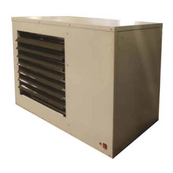
MODULATING, GAS‐FIRED, BALANCED FLUE OR
Please read this document carefully before commencing installation commissioning and/or servicing. Leave it with the user
Improper installation, adjustment, alteration, service or maintenance can cause property damage, injury or death. All work
must be carried out by appropriately qualified persons. The manufacturer does not take any responsibility in the event of
non‐observance of the regulation concerning the connection of the apparatus causing a harmful operation possibly resulting
in damage to the apparatus and/or environment in which the unit is installed.
Subject to modifications
POWER‐VENTED UNIT HEATER
VRA‐4E
INSTALLATION
COMMISSIONING
This appliance meets the following EC Directives
DIR 2009/142/EC : GAD
DIR 2014/30/EC : EMC
DIR 2014/35/EC : LVD
DIR 2006/42/EC : MD
or attached to the appliance or gas service meter after installation.
SERVICING
WARNING
1712VRA-4EGBEN
1712VRA‐4EGBEN, pag. 1/25
Advertisement
Table of Contents

Related Manuals for Nortek Reznor VRA20-4E


Summary of Contents for Nortek Reznor VRA20-4E
- Page 1 1712VRA-4EGBEN MODULATING, GAS‐FIRED, BALANCED FLUE OR POWER‐VENTED UNIT HEATER VRA‐4E INSTALLATION COMMISSIONING SERVICING This appliance meets the following EC Directives DIR 2009/142/EC : GAD DIR 2014/30/EC : EMC DIR 2014/35/EC : LVD DIR 2006/42/EC : MD Please read this document carefully before commencing installation commissioning and/or servicing. Leave it with the user or attached to the appliance or gas service meter after installation. WARNING Improper installation, adjustment, alteration, service or maintenance can cause property damage, injury or death. All work must be carried out by appropriately qualified persons. The manufacturer does not take any responsibility in the event of non‐observance of the regulation concerning the connection of the apparatus causing a harmful operation possibly resulting in damage to the apparatus and/or environment in which the unit is installed. Subject to modifications 1712VRA‐4EGBEN, pag. 1/25 ...
-
Page 2: Table Of Contents
TABLE OF CONTENTS 1.0 INTRODUCTION p 3 6.0 COMMISSIONING AND TESTING 1.1 Basic Information p 11 1.2 Warranty 6.1 Electrical Check 2.0 TECHNICAL DATA p 4 6.2 Gas Connection 2.1 Specifications 6.3 Suspension and Support 2.2 Dimensions 6.4 Lighting the Heater 3.0 GENERAL REQUIREMENTS ... -
Page 3: Introduction
This appliance is not intended for use by persons (including children) with reduced sensory or mental capacities or lack of experience and knowledge unless they have been given supervision or instructions concerning use of the appliance by a person responsible for their safety. -
Page 4: Technical Data
TECHNICAL DATA 2.1 Specifications Table 1 VRA-4E Gas category II2H3+ B22P Comb. Air & Flue, type B C12, C32, C62 Comb. Air & Flue, type C Connection collars Heat input Hs 13,33 26,42 31,63 43,95 54,38 61,08 73,25... -
Page 5: Dimensions
2.2 Dimensions Figure 1 250 min Flue Outlet Flue Inlet Gas Connection 500 min Electrical connections Service panel Suspension points (M10 female) VRA-4E 1/2"G 1/2"G 1/2"G 3/4"G 3/4"G 1298 3/4"G 1298 3/4"G 1298 3/4"G 1298 1022 3/4"G 1750 1100 1057... - Page 6 must not be used! Table 4 Min. installation clearances Figure 2a : Combustion air and flue pipe sockets VRA-4E Flue connector Access panel Non access side Bottom Rear* * Measure rear clearance from the back of the motor Table 5 Recommended mounting heights (m) (*) 30→-50 60-→100 120→145 VRA-4E Mounting...
- Page 7 3.3.2 Combustion air inlet pipe & flue pipe for balanced flue installation (Type C appliances) Balanced flue air heaters are designed to be fitted Figure 2b : with a combustion air inlet pipe that obtains outdoor Combustion air and flue pipe sockets, Type C air and a flue pipe that exhausts flue products to outdoors.
-
Page 8: Air Supply
3.4 Air supply 3.5 Air distribution It is important to ensure that there is an adequate air Follow recommended practice for building air supply at all times for both combustion and heating distribution. The following notes are of particular requirements. -
Page 9: Installation
INSTALLATION 4.1 Unpacking and preparation Flue pipe runs may be horizontal or vertical and Prior to dispatch, the air heater was operated and terminate either through the wall or roof. See tested at the factory. If the heater has incurred table 5 for maximum pipe length for an any damage in shipment, file a report claim within appliance installed as type B or table 6 for... -
Page 10: Gas Connection
4.4 Gas connection 4.5 Electrical connections 4.5 Electrical connection ATTENTION Do not use the appliance gas THIS APPLIANCE MUST BE EARTHED ! supply to balance or support any part of the appliance. IMPORTANT: If the reset button requires activating Connection to a gas network may only be carried for any reason the cause should be identified before out by appropriately qualified persons. -
Page 11: Commissioning And Testing
COMMISIONING/TESTING The whole of the gas service installation including The commissioning and testing may only be meter must inspected, tested carried out by appropriately qualified persons. soundness purged accordance with This section should be read and fully understood appropriate requirements by a qualified person. -
Page 12: Adjustments
6.4.2 To turn the air heater "OFF" for short periods Ascertain from section 1 of this document and Adjust the room thermostat to its lowest setting or the appliance data plate the correct operating 'OFF'. The fan will continue to run to cool the gas pressure for the air heater;... -
Page 13: Air Distribution System
6.9 Handing over 6.7 Air distribution system Upon satisfactory completion Adjust the air outlet discharge louvers to provide a commissioning testing, hand satisfactory spread of the warm air. Direct the air instructions user their towards the floor avoiding blowing directly on people representative. -
Page 14: Servicing Instructions
SERVICING INSTRUCTIONS IMPORTANT: Only appropriately qualified persons When any service is completed, be sure that may carry out servicing and fault finding on this gas components are reassembled correctly to ensure fired equipment. -
Page 15: Main Burner Removal
Removal & replacement of parts VRA-4E air heaters must only be fitted with After any service work has been Remember! authorized replacement parts. These heaters carried out, the air heater must be must use certificated spare parts to comply with fully commissioned. -
Page 16: Ignition System
8.3 Ignition system Flame sensor - Refer to figure 9 and locate the To access the ignition system, follow steps 1 to 3 in flame sensor. Disconnect the wire, remove the screw § 8.1. and the flame sensor. Clean with an emery cloth. Due to high voltage on the spark ATTENTION : wire and electrode, do not touch when energized. -
Page 17: Fault Finding
FAULT FINDING Fault finding may only be carried out by appropriately qualified persons Air heater does not operate and lock‐out indicator light is off Air heater does not operate and lock‐out indicator light is on 1712VRA‐4EGBEN, pag.. 17/25... - Page 18 1712VRA‐4EGBEN, pag.. 18/25...
- Page 19 1712VRA‐4EGBEN, pag.. 19/25...
-
Page 20: Parts List
PARTS LISTING VRA-4 E Part number Settings Delta P switch S3: 12 30 606177 200 238Pa out 250Pa in Delta P switch S3: 20 30 60617 185 175Pa out 203Pa in Delta P switch S3: 30/35/45/50/60/75 30 60621 175 1627Pa out 1767Pa in Delta P switch S3: 120/145... -
Page 21: Users Instructions
USER INSTRUCTIONS Operating If the thermal overheat control requires resetting How the air heater works Gas is burned by an and doing so restarts the air heater, wait until the atmospheric burner which fires into a heat exchanger. appliance warms to thermal equilibrium, to ensure The gas burner is controlled by a double gas valve via the overheat control does not lock out again. -
Page 22: Health & Safety Statement
HEALTH & SAFETY STATEMENT General Thermostat Under the Consumer Protection Act 1987 and Material: Illuminating Kerosene. Section 6 of the Health and Safety at Work Act Description: Sealed phial contains small 1974 we hereby provide the following information quantity in liquid form. - Page 23 CERTIFICATE EC DECLARATION OF CONFORMITY OF MACHINERY (Annex II 1 A of EC Machinery Directive 2006/42/EC) Nortek Global HVAC Belgium nv J&M Sabbestraat 130/A000 B‐8930 Menen, Belgium Hereby declares that the following gas‐fired unit heaters: VRA‐4E Types 12,20, 30, 35, 45, 50, 60, 75, 100, 120, 145 Complies with the requirements of the above mentioned machinery directive Complies with the requirements of further directives, namely GAD 2009/142/EC ‐ EMC 2014/30/EC – LVD 2014/35/EC the following harmonized standards have been applied: EN 1020: Non‐domestic gas‐fired forced convection air heaters for space heating not exceeding a ...
- Page 24 94,7 94,4 95,2 94,5 94,0 93,9 93,3 s,flow ErP seasonal space heating energy efficiency: η 74,2 72,1 72,2 72,2 72,2 73,3 72,1 72,5 72,1 72,3 72,8 Thermal efficiency at rated heating capacity [NCV]: η 93,0 91,0 89,7 90,1 90,8 91,5 90,2 91,0 91,0 91,5 92,2 * not required for electric warm air heaters Contact details: Nortek Global HVAC Belgium NV; +32 (0)56 52 95 11; J&M Sabbestraat 130/A000; B‐8930 Menen; West‐Flanders; Belgium; www.reznor.eu 1712VRA‐4EGBEN, pag.. 24/25 ...
- Page 25 NORTEK GLOBAL HVAC (UK) LTD Fens Pool Avenue Brierley Hill West Midlands DY5 1QA United Kingdom Tel. 01384 489 250 Fax. 01384 487 707 reznorsales@nortek.com www.reznor.co.uk Nortek Global HVAC is a registered trademark of the Nortek Global HVAC Limited. Because of continuous product innovation. Nortek Global HVAC reserves the right to change product specification without due notice 1712VRA‐4EGBEN, pag.. 25/25 ...
Need help?
Do you have a question about the Reznor VRA20-4E and is the answer not in the manual?
Questions and answers