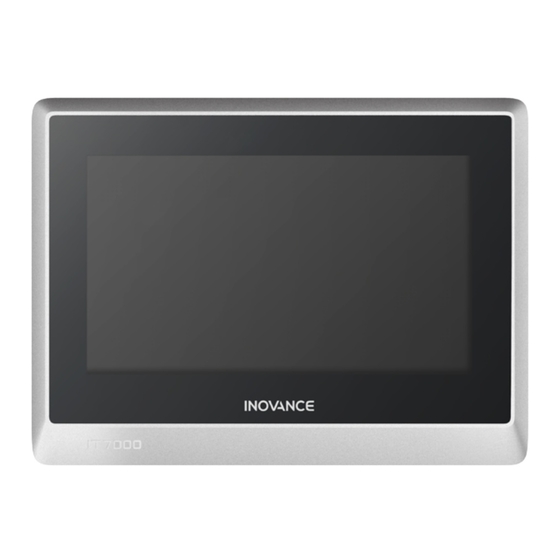
Summary of Contents for Inovance IT7000 Series
- Page 1 IT7070 HMI User Guide Suzhou Inovance Technology Co,. Ltd Address: No. 16 Youxiang Road, Yuexi Town, Wuzhong District, Suzhou Service line: 400-777-1260 Website: http://www.inovance.com Technical Support Documentation...
-
Page 2: Revision History
Read this guide carefully before using to ensure safety. For details on use of the user program development environment and design of user programs, see the help file of InouTouch PAD, a software tool developed by Inovance. Visit our website (www.inovance.com) for the latest version of the guide. - Page 3 4. Use this product according to the designated environment requirements. Damage caused by improper usage is not covered by warranty. 5. Inovance shall take no responsibility for any personal injuries or property damage caused by improper usage. ■ Safety Levels and Definitions DANGER The “DANGER”...
- Page 4 CAUTION Do not set any switch that may result in personal injury of the operator or equipment damage ◆ on the touch screen. A separate switch is required for important operation to avoid accidents caused by abnormal output or faults; Do not set any switch on the equipment to control safety operation, such as emergency stop.
- Page 5 CAUTION Cut off the main power supply before connecting the power supply of the equipment. Failure to ◆ comply may result in electric shock. The input power of the equipment is 24 VDC. If the power input is not within 24 VDC±20%, ◆...
-
Page 6: Product Information
1 Product Information 1.1 Appearance and Model Number ■ Appearance ■ Model Number 1.2 Basic Parameters Product Model Item IT7070E IT7070T IT7070S Cortex A8 600MHz Supported DRAM 128MB DDR3 Flash 128MB One Micro SD interface SD card slot (Supports Micro SD No SD card interface No SD card interface cards, push-push type) - Page 7 Product Model Item IT7070E IT7070T IT7070S COM1 (RS422/RS485) COM1 (RS422/RS485) Serial port COM2 (RS232) COM1 (RS422/RS485) COM2 (RS232) COM3 (RS485) One 10M/100M adaptive RJ45 Ethernet port Ethernet port No Ethernet port No Ethernet port Cable: within 100 meters, CAT5 and above Mini USB type One USB type B port B port...
-
Page 8: Installation Environment
2 Mechanical Design Reference 2.1 Installation Environment This equipment operates stably only within -10° C to 55° C (14° F to 131° F) (0℃ to 50℃ for IT7070S). Temperature out of this range may cause damage, malfunction or performance degradation of the HMI components. For special occasions, please consult your supplier;... -
Page 9: Installation Method
2.3 Installation Method 1) Align the equipment with the mounting holes in the mounting plate; 2) Put the 4 clasps (delivered with the equipment) into the 4 mounting holes in top and bottom sides or left and right sides of the equipment from the back of the mounting plate;... -
Page 10: Terminal Description
3 Electrical Design Reference 3.1 Terminal Description Name Description Name Description HMI 24 VDC power input The slave USB Power terminal Mini USB communication port to supply port download and debug user (A power connector is terminal programs in a PC included in the delivery) Communication port between HMI and... - Page 11 Name Description Name Description Ethernet communication Mounts a Micro SD card port (RJ45) for for data read/write and Micro communicating with a PLC project file download Ethernet SD card with a LAN port or a PC. port Note: No Micro SD card interface Note: IT7070S/IT7070T have interface is available in...
- Page 12 ● The 24 V power supply cable and communication cables must not be close to cables with strong interference, such as AC power cables and motor drive cables. A minimum distance of 30 cm is required; ● It is recommended to use a separate #14AWG conductor as the conductor of the grounding wire.
- Page 13 Pin Signal level RS422 RS422 Pin No. Signal Pin No. Signal Cable connection Inovance H1U/H2U/H3U RS422 IT7070/IT7100 HMI COM1[RS422] communication ports Compatible HMI Note: This cable is not suitable and Port Mitsubishi FX1N/2N/3U/3G RS422 for IT7150E. communication ports HMI user program In the HMI user project, set the COM1 port as “RS422/RS485”...
- Page 14 8-Pin Din Round Connector and Pin RS232, built-in RS232-RS422 RS422 Signal level switching circuit Pin No. Signal Pin No. Signal Cable connection Inovance H1U/H2U/H3U RS422 IT5xxx HMI COM2[RS232] communication ports Compatible HMI IT6xxxE HMI COM2[RS232] and Port Mitsubishi FX1N/2N/3U/3G RS422 IT7xxxT/E HMI COM2[RS232]...
-
Page 15: Ethernet Connection
HMI user program In the HMI user project, set the COM2 port as "RS232"; setting The HMI and PLC must have the same communication protocol and for this cable data format settings. ■ Precautions on Communication Connection 1) Cable requirements: Different cables are required for the connection of different external devices. -
Page 16: Programming Reference
5. Ethernet port or USB port: for uploading/downloading screen program 6. Operating system: Windows 7 or Windows 10 Connect an Inovance PLC to the port of the product as shown in the figure below. ■ Programming Cable (connecting with Inovance PLC) For this product, a miniUSB communication cable is used as the programming cable, which is available as an option from Invoance (order number: 15041200). -
Page 17: Touch Screen Calibration
5 Touch Screen Calibration If the touch screen becomes unresponsive or malfunctions, you can use the touch screen calibration program to fix the problem. ■ Start the Calibration Program Access the program through the system setup menu: After the HMI is powered on and the screen displays “Long press to enter the Setup screen”... -
Page 18: Warranty Agreement
If there is any problem during the service, contact us or our agent directly. You are assumed to agree on terms and conditions of this warranty agreement by purchase of the product. This agreement shall be interpreted by Inovance Technology.


Need help?
Do you have a question about the IT7000 Series and is the answer not in the manual?
Questions and answers
Excessive speed error