Table of Contents
Advertisement
Quick Links
Index/Introduction
1
1.1
Glossary and abbreviations ................................................................................................................................................................25
1.2
Safety notices......................................................................................................................................................................................25
2
2.1
General safety precautions.................................................................................................................................................................26
2.2
Installer's requisites.............................................................................................................................................................................26
2.3
Working clothes...................................................................................................................................................................................26
2.4
Permitted uses ....................................................................................................................................................................................27
3
General features
3.1
General description.............................................................................................................................................................................28
3.2
Technical characteristics.....................................................................................................................................................................29
3.2.1 Overall dimensions..............................................................................................................................................................................29
3.2.2 Technical data .....................................................................................................................................................................................29
3.2.3 Application fi eld ...................................................................................................................................................................................30
3.3
Preliminary operations ........................................................................................................................................................................30
3.3.1 Mounting tools.....................................................................................................................................................................................30
3.3.2 Checking the electrical installation .....................................................................................................................................................31
3.3.3 Preliminary checks..............................................................................................................................................................................31
4
4.1
Assembly on lintel ...............................................................................................................................................................................32
4.1.1 Installing the geared motor ................................................................................................................................................................34
4.1.2 Positioning the geared motors ...........................................................................................................................................................35
4.1.3 Installing the control unit .....................................................................................................................................................................36
4.2
Cantilevered assembly........................................................................................................................................................................38
4.3
Electrical connections ........................................................................................................................................................................40
4.3.1 Useful advice.......................................................................................................................................................................................40
4.3.2 Connecting the motor cables..............................................................................................................................................................40
4.3.3 Connecting the control accessories ...................................................................................................................................................40
4.3.4 Connection to the power network.......................................................................................................................................................40
4.3.5 Programming the functioning..............................................................................................................................................................41
4.4
Checking the functioning ....................................................................................................................................................................42
4.4.1 Local control functioning .....................................................................................................................................................................42
4.4.2 Centralised control functioning ..........................................................................................................................................................42
4.4.3 Obstacle recognition ...........................................................................................................................................................................42
4.5
Mounting the casing............................................................................................................................................................................42
4.5.1 Version with electric stop ....................................................................................................................................................................43
4.5.2 Version without electric stop ...............................................................................................................................................................44
5
5.1
Notes for the use .................................................................................................................................................................................45
5.1.1 What to do in case of power failure ....................................................................................................................................................45
- 24 -
Advertisement
Table of Contents

Related Manuals for Aprimatic Buongiorno


Summary of Contents for Aprimatic Buongiorno
-
Page 1: Table Of Contents
Index/Introduction Introduction Glossary and abbreviations ................................25 Safety notices......................................25 Safety precautions General safety precautions.................................26 Installer’s requisites.....................................26 Working clothes....................................26 Permitted uses ....................................27 General features General description.....................................28 Technical characteristics..................................29 3.2.1 Overall dimensions....................................29 3.2.2 Technical data .....................................29 3.2.3 Application fi eld ....................................30 Preliminary operations ..................................30 3.3.1 Mounting tools.....................................30 3.3.2 Checking the electrical installation ..............................31 3.3.3 Preliminary checks....................................31... -
Page 2: Introduction
Introduction 1.1 GLOSSARY AND ABBREVIATIONS This paragraph lists uncommon terms or terms having a meaning other than the common one as well as the abbreviations contained in the manual. The uncommon terms are:: • INTERVENTION ZONE zone circumscribing the area of installation where the presence of an exposed person may result in risks for the safety and the health of this person (Annex I, 1.1.1 Directive 89/392/EEC);... -
Page 3: Safety Precautions
Periodically check the proper functioning of the operator. Check it at regular intervals of maximum 12 months. • Use only genuine spare parts 2.2 INSTALLER’S REQUISITES The installation of Aprimatic products shall be entrusted to qualified technicians having the necessary technical skill. The operator shall meet the following criteria: •... -
Page 4: Permitted Uses
Safety precautions PERMITTED USES The BUONGIORNO operator has been designed to automate the motion of single or double-wing shutters regardless of the material they are made of (wood, aluminium, PVC) provided they fall within the dimensional limits (surface, width, weight) indicated in Table 3 section 3.2.3. -
Page 5: General Description
According to the type of shutter and the chosen assembly, APRIMATIC offers the following accessories:: C - Curved brackets (see Aprimatic S.p.A price-list) Recommended for the installation on shutters with a flat surface suitable for the mounting of the sliding guides necessary for the bracket operation. -
Page 6: Technical Characteristics
F e a t u r e s 3.2 TECHNICAL CHARACTERISTICS 3.2.1 Overall dimensions Assembly on lintel 430÷1500 130,5 121,4 62,8 Cantileveled assemly 62,8 43 0÷1500 121,4 130,5 Articulated brackets Curved brackets 3.2.2 Technical data Tab. 1 Technical data Tab. 2 Resistance to wind Power supply 230 V A.C. -
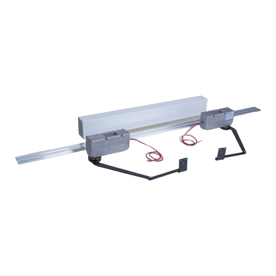
Page 7: Preliminary Operations
F e a t u r e s 3.3 PRELIMINARY OPERATIONS Open the packaging and check the presence of the following components: 11) Nylon clutch rings 1) Supporting rail 12) Clutch cover 2) Geared motor fixing inserts 13) Hexagonal head screws and washers for clutch 3) Geared motor 14) PVC casing 4) Geared motor locking screws... -
Page 8: Mounting Tools
DOWN Caution Before installing BUONGIORNO, it is better to dismount closing and locking accessories of the wings already fitted on them; if you want to hold them in position, make sure they do not hinder the functioning of the operator. -
Page 9: Installation
I n s t a l l a t i o n 4.1 ASSEMBLY ON LINTEL • Measure the width of the upper edge of the window aperture and check the length of the supporting rail. This length shall be such to allow keeping a maximum distance between its ends and the vertical walls of the window aperture of max. - Page 10 I n s t a l l a t i o n • With closed wings, position rail (1) on the lintel at the A - Outside heights given in the figure (12 mm between shutter B - Inside wing and rail). To this end, use the aluminium gauge (2) supplied as template.
-
Page 11: Installing The Geared Motor
I n s t a l l a t i o n 4.1.1 Installing the geared motor According to the type of shutter, the following brackets can be assembled to the geared motor (1): ≠ curved brackets (standard supplied); articulated brackets (upon request). •... -
Page 12: Positioning The Geared Motors
I n s t a l l a t i o n 4.1.2 Positioning the geared motors Curved brackets With curved brackets To obtain the correct position of geared motor (11) on the rail, proceed as follows: • Open the wings. •... -
Page 13: Installing The Control Unit
Installation 4.1.3 INSTALLING THE CONTROL UNIT Before the installation on the rail, prepare the electrical box as follows: • Fit the cable bushings (2), (3) and (4). Warning Close the free hole with the special plug (5) provided. • Fix both brackets (6) to the supporting rail using Single wing the two fl... - Page 14 I n s t a l l a t i o n • Hand-close the wings and TIGHTEN the arm clutch screws (8) (about 8 Nm torque). Warning Clutches are not adjustable and shall always be well tightened. Wrongly tightened screws do not allow for the actuation of the electronic current absorption control stopping the automatic operator (In any case, the operator stops after 40 sec.).
-
Page 15: Cantilevered Assembly
The use of the template allows keeping the minimum Ø distance between operator and lintel. It is possible to install the BUONGIORNO operator even at a greater distance from the lintel. However, in this case, it is necessary to respect the alignment... - Page 16 I n s t a l l a t i o n • Fit the stop inserts (3) supplied together with the supporting brackets into the central guide of the rail. Inserts have an obliged insertion direction. • Mark the position to drill the rail for the screw passage on the threaded holes on inserts (3).
-
Page 17: Electrical Connections
Installation ELECTRICAL CONNECTIONS Attenzione • The operator shall always be protected upstream by a 6A automatic differential switch with 30 mA actuation point and contact opening over 3 mm. • The electrical installation shall be in compliance with the regulations in force in the installation country. •... -
Page 18: Programming The Functioning
Installation 4.3.5 Programming the functioning Operator functions are programmed by positioning the jumpers as described below. Warning Turn off the machine for at least 20 seconds before changing the jumper position. • Jp1: • Jp2 & Jp3: destined for the delayed closing of the wing destined for the functioning with one or two wings. -
Page 19: Checking The Functioning
Installation CHECKING THE FUNCTIONING Warning Make sure that the clutch screws on the geared motors are well tightened (about 8 Nm torque). Information The first control accepted by the machine when turned on or reset is the OPEN control regardless of the position of the wings; all other controls are ignored with the exception of the centralised CLOSING control which remains active at all times. -
Page 20: Mounting The Casing
I n s t a l l a t i o n 4.5 MOUNTING THE CASING Before assembling the casing onto the rail, it is necessary to drill a slot having a minimum width of 25 mm and a length equal to the distance between wall and geared Geared motor shaft motor shaft plus 2 mm at the end of both PVC casings (1) or of the single casing, in case of single-wing shutters, as... -
Page 21: Version Without Electric Stop
(4) with slot oriented inwards and lock it with screw (7) and nut (5). • Cover the slot with the APRIMATIC label (6). Single-wing Double-wing - 44 -... -
Page 22: Notes For The User
Notes for the user 5.1 NOTES FOR THE USER The BUONGIORNO operator runs according to a “man presence” logic, say its motion persists as long as the user holds the control pushbutton pressed down. Warning During functioning, the user shall always check the shutter fitted with the BUONGIORNO operator.
Need help?
Do you have a question about the Buongiorno and is the answer not in the manual?
Questions and answers