Aiphone GT Series Installation Manual
Multi building system
Hide thumbs
Also See for GT Series:
- Quick start installation manual (24 pages) ,
- Installation manual (2 pages) ,
- Quick start installation manual (24 pages)
Table of Contents
Advertisement
The following manuals (in multi languages) of the GT system are also available from our website
http://www.aiphone.net/.
* The site can be accessed directly by reading the QR code on the right.
•
Operation manual
•
Installation manual
•
Setting manual
•
Quick start installation guide
•
Aiphone GT Setup Tool for Windows
Thank you for selecting Aiphone for your communication needs. Please read this manual carefully before installation, and
keep this in a safe place for future reference.
Please note that images and illustrations depicted in this manual may differ from the actual product.
GT SYSTEM
Multi Building System
INSTALLATION MANUAL
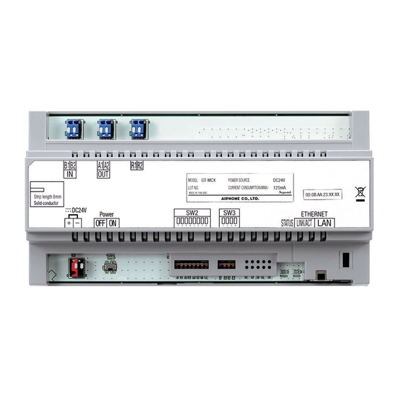
This manual explains how to install the multi-building control unit GT-MCX.
Refer to the installation manual for the GT SYSTEM/Standard & Expanded
System for installing the other GT system products.
SERVICE MANUAL
[QR code]
Advertisement
Table of Contents

Related Manuals for Aiphone GT Series


Summary of Contents for Aiphone GT Series
- Page 1 • Aiphone GT Setup Tool for Windows Thank you for selecting Aiphone for your communication needs. Please read this manual carefully before installation, and keep this in a safe place for future reference. Please note that images and illustrations depicted in this manual may differ from the actual product.
-
Page 2: Precautions
• Places near heating equipment or a boiler that varies in temperature. 4. For power supply, use Aiphone power supply model or model specifi ed • Places where dust, oil, chemicals or hydrogen sulfi de are present. -
Page 3: Table Of Contents
Table of Contents PRECAUTIONS ............................2 1 SYSTEM CONFIGURATIONS 1-1 Application examples ........................4 1-2 Multi building consisting of standard systems .................. 5 1-3 Multi building consisting of expanded systems ................6 1-4 Wiring distance ..........................8 2 COMPONENTS ............................ 9 3 MOUNTING 3-1 Cables .............................. -
Page 4: System Configurations
SYSTEM CONFIGURATIONS The GT system can be confi gured over an IP network so multiple buildings can be connected and controlled centrally as a large-scale system. There can be a maximum of 5,000 residential/tenant stations in the system. A multi building system consists of tenant and main sections, and a section consists of a standard or expanded system. All sections can be confi... -
Page 5: Multi Building Consisting Of Standard Systems
: CAT5e/6 cable (100BASE-TX) DP: Distribution Point Residential/tenant trunks 1 to 4 [max. 48 stations (max. 25 per trunk)]* (Not provided by Aiphone except for Europe * Refer to section 4 "WIRING" for details about the residential/tenant stations. and North America.) *1: Refer to Standard &... -
Page 6: Multi Building Consisting Of Expanded Systems
SYSTEM CONFIGURATIONS Multi building consisting of expanded systems The following is a multi building system confi guration example that consists of expanded systems as tenant and main sections. Refer to the installation manual GT SYSTEM/Standard & Expanded System for details about the expanded system confi guration. *1: Refer to Standard &... - Page 7 GT-DMB-N/ GT-DMB-LVN unit GT-DMB-LVN GT-BC PS24 PS24 Common trunk line 1 Common trunk line 2 DP: Distribution Point (Not provided by Aiphone except for Europe and North America) Audio signal line Video signal line Power supply line CAT5e/6 cable (100BASE-TX)
-
Page 8: Wiring Distance
SYSTEM CONFIGURATIONS Wiring distance The following diagrams show the wiring distances between the multi-building control unit GT-MCX and main section devices only. Refer to the installation manual GT SYSTEM/Standard & Expanded System for wiring distances between residential/tenant stations. Standard system Expanded system GT-VBC GT-VBC... -
Page 9: Components
(maximum 2 "common" trunk lines) *1: DP = Distribution Point (Not provided by Aiphone except for Europe and North America.) Do not route a CAT5e/6 cable outdoors from a multi-building control unit directly. When routing a CAT5e/6 cable outdoors from a switching hub, use a model that supports outdoor wiring. -
Page 10: Mounting
MOUNTING Cables • Use PE (polyethylene)-insulated PVC jacket cable. Parallel or jacketed 2-conductor, mid-capacitance non-shielded cable is recommended. (x2) • Never use individual conductors, twisted pair cable or coaxial cable. To connect low voltage wires, either crimp them with a crimp sleeve or solder them, and then insulate by covering with insulating tape. -
Page 11: Mounting The Multi-Building Control Unit Gt-Mcx
MOUNTING Mounting the multi building control unit GT-MCX Mount the unit on the included DIN rail. Click the unit into place. When removing the unit, pull the lock release lever down. The GT-MCX cannot be mounted directly to a wall surface. DIN rail (included) DIN rail Lock release lever... -
Page 12: Wiring
Common area Guard station Video bus control unit GT-VBC DP (Distribution Point) Guard station (Not provided by Aiphone except for Europe and North America.) Refer to the installation manual GT SYSTEM/ MODE Standard & Expanded System section 4-2 EXPAND STANDARD for detailed connection diagrams. - Page 13 *1: DP (Distribution Point) wiring example • When using a distribution terminal block, it is not provided by Aiphone except for Europe and North America. • After making connections, be sure to check that there are no disconnected or loose parts.
- Page 14 Common area Guard station Video bus control unit GT-VBC DP (Distribution Point) Guard station (Not provided by Aiphone except for Europe and North America.) Refer to the installation manual GT SYSTEM/ MODE Standard & Expanded System section 4-2 EXPAND STANDARD for detailed connection diagrams.
- Page 15 DP (Distribution Point) wiring example • When using a distribution terminal block, it is not provided by Aiphone except for Europe and North America. • After making connections, be sure to check that there are no disconnected or loose parts.
-
Page 16: Multi Building Consisting Of Expanded Systems
WIRING Multi building consisting of expanded systems The following is a connection diagram example of a multi building Tenant section (expanded system) system consisting of expanded systems as tenant and main sections. * The wiring methods differ depending on the equipment used. Refer to the installation manual GT SYSTEM/Standard &... - Page 17 WIRING NOTES: Each pair of wires should be in a separately jacketed cable Do not use the unused terminals and ports for other purposes. • (audio, video, and power wiring). In order to prevent miswiring, label both ends of each cable with •...
- Page 18 WIRING Main section (expanded system) Common trunk line 1 Guard station Refer to the installation manual GT SYSTEM/Standard & Expanded System section 4-2 for detailed connection diagrams. Guard station PS24 Entrance stations Entrance station 7 Refer to the installation MODE manual GT SYSTEM/ OUT 1 EXPAND...
- Page 19 WIRING PS24 PS-2420DM 24 V DC2A 230 V AC 50/60 Hz PS-2420 PS-2420S PS-2420UL Common trunk line 2 PS-2420BF (guard station) 24V DC 100V - 240V - 50/60 Hz MODE OUT 1 EXPAND STANDARD DC24V : Audio signal line : Video signal line GT-VBC : Power supply line : CAT5e/6 cable...
-
Page 20: Switch Settings
SWITCH SETTINGS The multi building control unit, GT-MCX, needs to be initially set up via the DIP switches before powering on. The IP address will be assigned based on the section ID setting. (192.168.1.50 + Section ID) Confi guration will then need to be completed using the GT Setup Tool on a PC. * Refer to the GT SYSTEM Multi Building System Setting manual for details about confi... - Page 21 SWITCH SETTINGS Section ID setting Set the section ID (1 to 32) for this unit by the combination of the switch 2 Section ID to 6 settings, as shown below. * Refer to 1 SYSTEM CONFIGURATIONS for details about "section". 1 2 3 4 5 6 7 8 Make sure not to repeat the same ID.
-
Page 22: Check For Installation
CHECK FOR INSTALLATION When checking operation after system installation shows a malfunction in spite of no error in equipment terminal connections, check for the following "grounding point" and "ground fault" in wiring. Tools required: Analog tester NOTES: A digital tester cannot make a precise reading. •... -
Page 23: Checking "Ground Fault" With Tester
CHECK FOR INSTALLATION Checking "ground fault" with tester What is “ground fault”? "Ground fault" means the state where internal copper wire is touching a metal part (ground) in the building because the coating on the wiring of the intercom system is peeled off. This may cause the equipment to malfunction. Being in the ground fault state, the whole system will be damaged seriously by a "power surge."... -
Page 24: Regulations
WARRANTY Aiphone warrants its products to be free from defects of material and workmanship under normal use and service for a period of 2 years after delivery to the ultimate user and will repair free of charge or replace at no charge, should it become defective upon which examination shall disclose to be defective and under warranty.
Need help?
Do you have a question about the GT Series and is the answer not in the manual?
Questions and answers