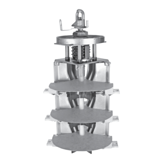
Summary of Contents for Eaton COOPER POWER LS4R Series
- Page 1 COOPER POWER OEM Equipment SERIES Effective March 2016 MN800002EN Supersedes June 2015 Sectionalizing switch installation instructions...
- Page 2 CONTENTS OF THIS DOCUMENT SHALL NOT BECOME PART OF OR MODIFY ANY CONTRACT BETWEEN THE PARTIES. In no event will Eaton be responsible to the purchaser or user in contract, in tort (including negligence), strict liability or other- wise for any special, indirect, incidental or consequential damage or loss whatsoever, including but not limited to damage or...
-
Page 3: Table Of Contents
Contents SAFETY INFORMATION Safety information ................iv PRODUCT INFORMATION Introduction . -
Page 4: Safety Information
FOR LIFE FOR LIFE Eaton meets or exceeds all applicable industry standards relating to product safety in its Cooper Power™ series products. We actively promote safe practices in the use and maintenance of our products through our service literature, instructional training programs, and the continuous efforts of all Eaton employees involved in product design, manufacture, marketing, and service. -
Page 5: Product Information
Upon receipt of a sectionalizing switch, Introduction inspect it thoroughly for damage and loss of parts incurred Eaton's Cooper Power™ series four-position sectionalizing during shipment. If damage or loss is discovered, file a loadbreak switch is designed for use in transformer oil, claim with the carrier immediately. -
Page 6: Standards
Electrical ratings Table 1. Ratings and Characteristics per IEEE Std C37.71™- Table 2. Ratings and Characteristics per IEC 60265-1 – 2001 standard 1998 Units 12.5 kA Rated Switches Units 16 kA Rated Switches To IEEE Std C37.71™ - 2001 To IEC 60265-1 - 1998 standard Switch Rating Rated Voltage... -
Page 7: Dimensional Information
Dimensional information Ø .44" (11 mm) 8.32" (211 mm) MTG. HOLES 8.35" (212 mm) TANK WALL .89" 4.38" (23 mm) (111 mm) 5.15" (131 mm) NOTES 5.40" 2 and 3 (137 mm) BARRIER Ø .39" HOLE TANK SEALING (10 mm) GLAND FURNISHED 2.75"... -
Page 8: Installation Procedure
All parts should be inspected for damage before using. If Mounting Bolts 60-100 in-lbs (7-11 Nm) there is evidence of physical damage, the unit should not be installed unless approved by your Eaton representative. [3/8" Dia.(10 mm)] Plastic Mounting Nut 60-120 in-lbs (7-14 Nm) -
Page 9: Ring-Mount Assembly
Should clarification or further HANDLE (FURNISHED) information be required for the user’s purposes, contact your Eaton representative. SPRING All energized parts of the switch must be under oil and (FURNISHED) LIMIT PLATE... -
Page 10: Wiring Schematics
Table 6. Wiring Schematics POSITION 4 POSITION 2 POSITION 3 SCHEMATIC SCHEMATIC SCHEMATIC VIEW OF POSITION 1 SWITCH HANDLE SWITCH HANDLE SWITCH HANDLE CONTACTS FROM ROTATED FRONT SCHEMATIC ROTATED ROTATED TYPICAL DECAL SWITCH FRONT (HANDLE) 90 CLOCKWISE AS SHIPPED AND AS 90 CLOCKWISE 90 CLOCKWISE TYPE... -
Page 11: Lead Training
ARC CLEARANCE ZONE 3.50" (89 mm) 1.75" (45 mm) MINIMUM MINIMUM 7 .0" (178 mm) RADIUS ALL AROUND ARC CLEARANCE ZONE (FRONT VIEW) Figure 6. Arc clearance zone. CAUTION WELD PINS (4) This illustrated decal in Figure 7 is typical of some (FOR V-blade switches only. -
Page 12: Operation
Switching can be accomplished in less than one obligations which may be attributable to Eaton's Cooper cycle, and should be performed with a hotstick. Power Systems Division. - Page 13 X = 36 Y = 0 WARNING 3.00" DIAMETER 2.00" (76 mm) (51 mm)* +0.030 1.320" TYPICAL Hazardous voltage. - 0.000 1.50" +0.8 (33.5 mm (38 mm) - 0.0 Do not operate loadbreak equipment if a fault DIA. HOLE TYPICAL •...
- Page 14 This page is intentionally left blank. SECTIONALIZING SWITCH INSTALLATION INSTRUCTIONS MN800002EN March 2016...
- Page 15 This page is intentionally left blank. SECTIONALIZING SWITCH INSTALLATION INSTRUCTIONS MN800002EN March 2016...
- Page 16 Waukesha, WI 53188 United States Eaton.com/cooperpowerseries © 2016 Eaton All Rights Reserved Eaton is a registered trademark. For Eaton's Cooper Power series product Printed in USA information call 1-877-277-4636 or visit: Publication No. MN800002EN Rev 01 All trademarks are property www.eaton.com/cooperpowerseries.


Need help?
Do you have a question about the COOPER POWER LS4R Series and is the answer not in the manual?
Questions and answers