
Related Manuals for ero electronic DPS


Summary of Contents for ero electronic DPS
- Page 1 DIGITAL PANEL INDICATOR INSTRUCTION MANUAL 170.MAN.DPS.E00 0,5.5 - 97 / 3 B...
- Page 2 DIMENSIONS AND PANEL CUT-OUT + 0.8 mm - 0.0 mm + 0.8 mm - 0.0 mm HORIZONTAL MOUNTING HORIZONTAL MOUNTING HORIZONTAL MOUNTING : Min distance between cut outs : 20 mm HORIZONTAL MOUNTING HORIZONTAL MOUNTING PACKING OF MORE INSTRUMENT IN A SINGLE CUT OUT PACKING OF MORE INSTRUMENT IN A SINGLE CUT OUT PACKING OF MORE INSTRUMENT IN A SINGLE CUT OUT PACKING OF MORE INSTRUMENT IN A SINGLE CUT OUT...
- Page 3 CONTENTS CONTENTS CONTENTS CONTENTS CONTENTS SECTION 1 GENERAL INFORMATION SECTION 1 GENERAL INFORMATION SECTION 1 GENERAL INFORMATION SECTION 1 GENERAL INFORMATION SECTION 1 GENERAL INFORMATION SECTION 5 SECTION 5 SECTION 5 SECTION 5 SECTION 5 INSTRUMENT CALIBRATION INSTRUMENT CALIBRATION INSTRUMENT CALIBRATION INSTRUMENT CALIBRATION INSTRUMENT CALIBRATION INTRODUCTION...
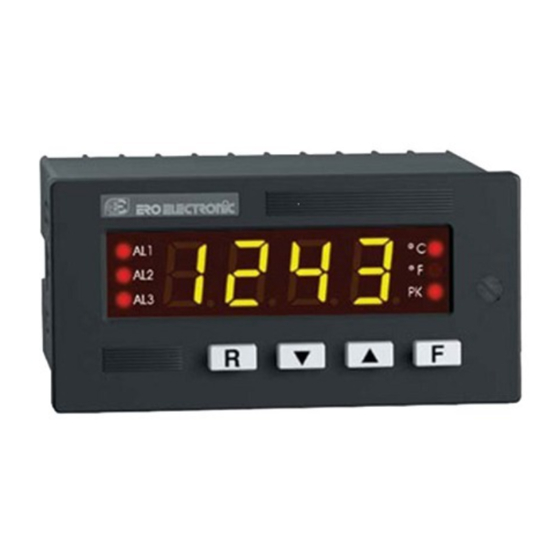
- Page 4 PC/ABS black color; self-extinguishing degree : V-0 1.1 INTRODUCTION according to UL. The DPS is a family of digital panel indicators developed with a Front panel : IP 54 protection (IEC 529 and CEI 70-1). variety of features for the solution of field problems.
- Page 5 Conversion: dual slope integration. Standard ranges: see table, others on request. Resolution: 25000 counts Calibration : according to IEC 584-1 (if not specified) Sampling time: 100 ms typical. STANDARD RANGES TABLE Display updating time: 400 ms typical. Ranges NOTE Accuracy: + 0.1 % fsv + 1 digit @ 25 °C ambient temperature. type Common mode rejection ratio: 120 dB @ 50/60 Hz.
- Page 6 B) Linear input C) RTD (Resistance Temperature Detector) Input: for RTD Pt100 Ω and Ni 100 Ω, 3 wire connection with °C/°F Input type: See table below Readout: keyboard programmable between -1999 and +9999. selectable by front pushbuttons. Input circuit: current injection (100 µA). Linearization: input signal may be linearized by setting up to 9 automatic compensation up to 3 Ω/wire with no breakpoints (10 segments) on the input span.
- Page 7 1.2.3 ALARMS 1.2.4 ADDITIONAL FUNCTIONS Number of alarms: two independent Peaks detection : visualization of the max. and min. value meas- Threshold: from 0 to 100 % of the readout span. ured by the instrument Hysteresis: programmable from 0.1 to 5.0 % of the readout span. Digital filter: it is possible to set a digital filter on the displayed value with a time constant of 0.4, 1, 2, 3, 4 or 5 s.
- Page 8 1.3.2 ANALOG RETRANSMISSION MODEL 1.4 CODING DPS = Digital panel indicator Isolated analog retransmission of the displayed value. Scaling: programmable between -1999 and 9999 Output type: 1) 0-20 mA or 4-20 mA, max. load 500 Ω, optoisolated POWER SUPPLY 2) 0-10 V, minimum load 5000 Ω, optoisolated...
- Page 9 LABELS MODEL 1.5.1 IDENTIFICATION LABEL The instrument identification label , see Fig. 1.1, is located externally STATUS: XX XX on the top rear of the housing. It contains the following information: POWER SUPPLY: 100/240 V AC INPUT : TC - RTD - MV - MA -V a) The instrument Model Number on the left side column.
- Page 11 SECTION 2 INSTALLATION 2.1 MOUNTING Select a mounting location where there is minimum vibration and the ambient temperature must be between 0 and 50 °C. The instrument can be mounted on a panel up to 15 mm thick with a cut out of 45 x 92 mm +0.8 mm Remove the two mounting brackets from...
- Page 12 2.2 WIRING GUIDE LINES A) POWER LINE Connections are to be made with the instrument housing installed in its proper location. 100 V to 120 V AC or 24 V AC/DC LINE NEUTRAL REMOTE EARTH PWS SUPPLY M0248-01 LOGIC mA/V INPUT Fig.
- Page 13 B) INPUTS Fig. 2.5 RTD INPUT WIRING NOTE: Don’t run RTD wires together with power cables. Fig. 2.4 THERMOCOUPLE INPUT WIRING If shielded cable is used, the shield must be grounded at one point only. Use copper wires with appropriate size (see "PRODUCT NOTE: Don’t run input wires together with power cables.
- Page 14 TABLE 1: THERMOCOUPLE COMPENSATING CABLE COLOUR CODES. Thermocouple British American German French Material BS 1843 ANSI MC 96.1 DIN 43710 NFE 18-001 Copper White Blue Yellow Constantan Blue Brown Blue Blue Blue Brown Blue Iron Yellow White Yellow Constantan Blue Blue Black Black...
- Page 15 2-wire transmitter without power supply 2-wire transmitter with power supply 4-wire transmitter with power supply POWER Fig 2.6 mA INPUT WIRING NOTE: Don’t run input wires together with power cables. If shielded cable is used, the shield should be grounded at one point only (see fig. 2.6).
- Page 16 2-wire transmitter 4-wire transmitter 2-wire transmitter 4-wire transmitter without power supply with power supply without power supply with power supply POWER POWER Fig. 2.7 mV INPUT WIRING Fig. 2.8 V INPUT WIRING NOTE: Don’t run input wires toghether with power cables. NOTE: Don’t run input wires toghether with power cables.
- Page 17 C) EXTERNAL ALARM RESET OR HOLD FUNCTION E) OUTPUTS It is possible to reset both alarms of the instrument or hold the E.1 ALARMS RELAY OUTPUT measured value by an external switch. Fig. 2.11 ALARM 1 RELAY WIRING Fig. 2.9 - EXTERNAL ALARM RESET WIRING D) LOCAL / REMOTE OPERATION It is possible to operate the instrument in local mode or in remote mode.
- Page 18 E 1. INDUCTIVE LOADS LOAD RESISTOR RESIST. AND Switching inductive loads, high voltage transients may occur. CURRENT (µF) (Ω) POWER (W) CAPAC. VOLTAGE These transients may damage the internal contacts, PCB or affect the performance of the instrument. In this care an external snubber <...
- Page 19 E 1.2 EXTERNAL LOADS WITH VERY LOW HOLDING E.2 ANALOG RE-TRANSMISSION CURRENT It may happen that the current flowing through the snubber network, when the contact is open, is sufficient to energize the external load (normally a contactor). A similar problem may occur when driving solid state relay with the internal relay of the instrument.
- Page 20 SERIAL INTERFACE A'/A A/A' RS-485 interface allows to connect up to 31 instrument with the remote master unit. See Fig. 2.17. B'/B B/B' A'/A A/A' COMMON B'/B B/B' COMMON Fig. 2.16 - RS-485 WIRING The cable length must not exceed 1.5 km at 9600 BAUD. NOTE: The following report describes the signal sense of the voltage appearing across the interconnection cable as defined by EIA for RS-485.
- Page 21 Logic voltage SERIAL INTERFACE Fig. 2.18 - LOCAL/REMOTE CONTACT WIRING A contact on the rear terminal block (terminals 18 and 19) is used to switch the instrument control from a master device to local mode or viceversa. In case of emergency, the operator must regain control on the instrument by a switch (B) connected in series to the master control (A) and positioned near the instrument.
- Page 23 SECTION 3 INSTRUMENT CONFIGURATION 3.1 FRONT PANEL DESCRIPTION...
- Page 24 3.1.1 INDICATORS 3.1.2 DISPLAYS AL 1 - AL 2 NUMERICAL DISPLAY Indicator OFF = no alarm condition Indicator ON = alarm condition The numerical display shows continuously the process variable in eng. units. During configuration and calibration set up, this display is used, in PK H addition to the alphanumerical display, to show the parameters Indicator OFF...
- Page 25 3.1.3 KEYBOARD DESCRIPTION Alarm 1 manual reset To increase the parameter value or select peak high visualization Alarm 2 manual reset To decrease the parameter value or select peak low visualization To select all the parameters . They are used to reset peak high Pushing the F pushbutton the parameters will be and peak low and restart the peak shown sequentially on the displays and, at the...
- Page 26 3.2 INSTRUMENT CONFIGURATION For configuration procedure, the internal DIP SWITCHES, mounted on CPU card, must be positioned as follows: SW1 = OFF SW2 = ON Fig. 3.1...
- Page 27 3.2.1 PRELIMINARY HARDWARE SETTINGS Before reassembling the instrument, make sure that all the necessary hardware settings are made as detailed below: For the input selection, the dip switches V2 must be setted as follows mA/TC/mV...
- Page 28 For alarms output, J250 and J251 must be setted as follows: For auxiliary power supply set the jumpers J232, J233, J234, J235 and J236 as follows: 10 V 12 V 24 V Pos. output output output output J232 close open open open J233...
- Page 29 For analog retransmission, set the jumpers J104, J105 and J107 as follows: J107 J104 J105 Voltage output J107 J104 J105 mA output...
- Page 30 3.2.2 CONFIGURATION PROCEDURE 3.2.3 PARAMETERS LIST The following is the complete parameters sequence. Once the internal dip switches have been positioned as described Some parameters may not be shown according to the previous in Fig. 3.1 proceed as follows: parameters setting. 1.
- Page 31 3) TC TYPE 3.a) RTD TYPE The display will show " tc " followed by: The display will show "rtd " followed by: PT = PT 100 Ω K = NiCr/NiAl TC (IEC 584-1) NI = Ni 100 Ω J = Fe/CuNi TC (IEC 584-1) Jd = Fe/CuNi TC (DIN 43710 - 1977) Push pushbuttons to set the desired RTD type.
- Page 32 4) LINEAR INPUT TYPE 4.b) DECIMAL POINT POSITION The display will show "IN" preceded by: The display will show "dP" preceded by: - - - -. = no decimal figure 0.20 = 0-20 mA - - -.- = one decimal figure 4.20 = 4-20 mA - -.- - = two decimal figures...
- Page 33 4.e) ENGINEERING UNIT 4.g) INPUT VALUE OF THE FIRST BREAK POINT The display will show "En.Un" followed by: The display will show "I1" preceded by a number between 00.01 °C = °C = normal m and 99.99 . °F = °F = Ampere This number show the input value of the first break point in percent = pH...
- Page 34 B) The low limit of the input break point is 0.01 more than the 6) FREQUENCY SETTING previous input break point while the upper limit is 99.99. The DPS with frequency input is not jet available so that all the informations related with frequency input setting are skipped. Readout...
- Page 35 8) OPTIONS 9.a) RETRANSMISSION MINIMUM SCALE VALUE The display will show "OPtn" followed by: The display will show "LR" preceded by a number between -1999 and 9999. 0 = no option provided (go to step 15) The decimal point is positioned as programmed at step 4b or 6a. 1 = 2 alarms (go to step 11) No decimal point is provided for TC or RTD inputs.
- Page 36 10) SERIAL INTERFACE ADDRESS Using pushbuttons it is possible to select the desired byte The display will show "Ad" preceded by a number. format. Using pushbutton it is possible to select the desired Push the F pushbutton to memorize the new choice and go to the instrument address from 0 to 31.
- Page 37 12) ALARM 2 Same as alarm 1 15) END At the end of configuration procedure the display will show "COnF" 13) FILTER ON THE ALARM THRESHOLD and it is possible to review the parameter setting or go to the The display will show "FILt" followed by a number. operating mode.
- Page 39 Usually the display show the measured value and its engineering 4.1 PRELIMINARY unit. After the configuration procedure, it is possible to make the DPS Pushing pushbutton it is possible to visualize the maximum peak operative by setting the internal dip switches mounted on CPU (see value (peak high) measured by the instrument (the "PK H"...
- Page 40 4.2.2 MANUAL RESET OF THE ALARMS 4.2.3 ALARMS THRESHOLD SETTING If the alarm has been configured as a latched alarm, the alarm status The visualization of the alarms threshold is always possible while its ( "ALx" indicator lit and relay deenergized) persists also after the modification must be done in accordance to the programmed safety alarm condition disappears.
- Page 41 B.2) Pushing F pushbutton the alarm threshold will be shown on 4.2.4 HOLD FUNCTION the numerical display while alphanumerical display will show "A1". The HOLD function allows to stop data acquisition and hold the Push pushbuttons and set the desired value. displayed value.
- Page 42 SECTION 5 INSTRUMENT CALIBRATION PROCEDURES 5.1 DIP SWITCHES LOCATION To start with the calibration procedure, the internal DIP SWITCHES , mounted on CPU card, must be positioned as shown at left: NOTE: during calibration procedure the serial communication interface will be disabled. SW1 = ON SW2 = OFF Fig.
- Page 43 5.2 GENERAL GUIDE LINES FOR CALIBRATION RESOLUTION 1) For TC, mV input: 1 µV 2) For current input: 0.2 µA For a good calibration it is necessary to proceed as follows: 3) For RTD input: 10 mΩ a) - The instrument under calibration should be mounted in its case 4) For could junction compensation: better then 0.1 °C in order to keep the internal temperature constant.
- Page 44 To go to the next parameter without modify the calibration, push F 5.3.2 CALIBRATION PROCEDURE pushbutton when the display is showing "OFF" . To set parameter calibration, push F pushbutton when the display All the instruments are originally calibrated by means of calibrators show "ON".
- Page 45 HOW TO PROCEED C 1 - CURRENT INPUT MAXIMUM RANGE VALUE. Push the F pushbutton to visualize the first calibration symbol on a) Set 20,000 mA on the calibrator (see Fig. 5.2). the display. Depress, in sequence, F pushbutton until the desired b) Push pushbutton, the display will show "ON"...
- Page 46 C 2 - 0 - 5 V INPUT MINIMUM RANGE VALUE C 3 - 0 - 5 V INPUT MAXIMUM RANGE VALUE. a) Connect the instrument to the calibrator as shown in Fig. 5.3. a) Set 5,000 V on the calibrator (see Fig. 5.3). b) Set 0.000 V DC on the calibrator (even if the minimum range b) Push pushbutton, the display will show "ON"...
- Page 47 C 4 - 0 - 10 V INPUT MINIMUM RANGE VALUE C 5 - 0 - 10 V INPUT MAXIMUM RANGE VALUE. a) Connect the instrument to the calibrator as shown in Fig. 5.4. a) Set 10,000 V on the calibrator (see Fig. 5.4). b) Set 0.000 V DC on the calibrator (even if the minimum range b) Push pushbutton, the display will show "ON"...
- Page 48 C 6 - TC, mV INPUT MINIMUM RANGE VALUE C 7 -TC, mV INPUT - MAXIMUM RANGE VALUE a) Provide connections between calibrator and instrument under a) Set the calibrator to 60.000 mV (see Fig. 5.5). test as shown in Fig. 5.5. b) Push pushbutton, the displays will show "ON"...
- Page 49 C 8 - RTD INPUT MINIMUM RANGE VALUE C 9 - RTD INPUT MAXIMUM RANGE VALUE a) Set the resistance box to 500.00 Ω (see Fig. 5.6). a) Connect a resistor box as shown in Fig. 5.6. b) Set 0.00 Ω on the resistor box. b) Push pushbutton, the displays will show "ON"...
- Page 50 C J COLD JUNCTION COMPENSATION COLD JUNCTION COMPENSATION CHECK NOTE: make sure that C6 and C7 parameters are correctly The display will show "RJ" and the cold junction temperature in calibrated before CJ calibration. tenths of °C. a) Measure the temperature close to terminals 1 and 3 using an Make sure that the display readout is equal to the value read on appropriate instrument, for instance, a MEMOCAL.
- Page 51 d) Depress F pushbutton. The instrument memorizes the above C H - ANALOG RETRANSMISSION MAXIMUM RANGE VALUE value as zero. The display will show now "C H" which means that the instru- a) Push pushbuttons until the output of the instrument ment is ready for next calibration step.
- Page 53 SECTION 6 DEFAULT PARAMETERS SETTING 6.1 PRELIMINARY DEFAULT CONFIGURATION PARAMETERS The instrument is delivered with a default parameters sets stored and Power supply frequency 50 Hz usable, in every moment, for clear all the memories. Input type Different parameters sets are provided for configuration, calibration TC type and operative modes but the memorization follows the same Pt 100 Ω...
- Page 54 Retransmission minimum scale value -1999 DEFAULT CALIBRATION PARAMETERS Retransmission maximum scale value 9999 Digital filter on the analog retran. None The default calibration parameters allow to verify the correct working Serial interface address of the instrument but they are not calibration parameters. 10.a Baud rate 19200...
- Page 55 SECTION 7 SECTION 7 SECTION 7 ERROR MESSAGES ERROR MESSAGES ERROR MESSAGES 7.2 OPEN INPUT CIRCUIT 7.2 OPEN INPUT CIRCUIT 7.2 OPEN INPUT CIRCUIT 7.2 OPEN INPUT CIRCUIT 7.2 OPEN INPUT CIRCUIT SECTION 7 SECTION 7 ERROR MESSAGES ERROR MESSAGES This instrument is able to identify the open circuit for 4-20 mA, 1-5 V, 2-10 V, TC and RTD inputs.
- Page 56 7.4 ERROR DESCRIPTIONS 7.4 ERROR DESCRIPTIONS 7.4 ERROR DESCRIPTIONS 7.4 ERROR DESCRIPTIONS 7.4 ERROR DESCRIPTIONS E101 E101 E101 E101 E101 Incorrect configuration data in EAROM memory. It may appear at instrument switching on in operative mode. E001 E001 E001 E001 E001 The instrument does not start to operate.
- Page 57 E201 E201 E201 E201 E201 E214/E215 E214/E215 E214/E215 E214/E215 E214/E215 Incorrect calibration data in EAROM memory. Could junction calibration errors. It may appear at instrument switching on in operative mode. The instrument measures a compensation temperature less than The instrument does not start to operate. -20 °C (E214) or higher than +70 °C (E215).
- Page 58 E218 E218 E218 E218 E218 E311/E312 E311/E312 E311/E312 E311/E312 E311/E312 Too big initial scale value or negative full scale value. Autozero errors. It may appear during input calibration when the instrument check the The instrument measures an internal autozero value too negative input calibration and detects an initial scale value higher than 14,5 (E311) or too positive (E312).
- Page 59 E401 E401 E401 E401 E401 The instrument detects the incorrect access to a protected memory area (this error may be generated by a big noise only). After 2 seconds the instrument restarts automatically. Verify configuration and calibration parameters. E402 E402 E402 E402 E402...
- Page 61 INPUT LINEARIZATION INPUT LINEARIZATION Serial No........Tag No........INPUT LINEARIZATION INPUT LINEARIZATION INPUT LINEARIZATION Measure READOUT...
- Page 62 Serial No........Tag No........INPUT LINEARIZA INPUT LINEARIZA INPUT LINEARIZATION BY BREAKPOINTS INPUT LINEARIZA INPUT LINEARIZA TION BY BREAKPOINTS TION BY BREAKPOINTS TION BY BREAKPOINTS TION BY BREAKPOINTS breakpoint Input in % Input in eng. Readout NOTES units Initial input rang value...
- Page 63 ERO Electronic Nederland U.S.A. Ganieelan 4 BRASIL 2404 CH Alphen a/d Rijn AMERICAN ERO Electronic Corp ERO ELECTRONIC DO BRASIL Industria e BARRINGTON, ILL. 60010 Tel. 0172-420400 Comercio Ltda. Tel. 0847-382-0881 Fax. 0172-420395 Rua Garibaldi, 659 - Conj. 202 sales@eroelectronic.nl...
Need help?
Do you have a question about the DPS and is the answer not in the manual?
Questions and answers