
Subscribe to Our Youtube Channel
Related Manuals for ero electronic DPL


Summary of Contents for ero electronic DPL
- Page 1 DIGITAL PANEL INDICATOR with linear inputs INSTRUCTION MANUAL 170.MAN.DPL.E00 0,1.2 - 99 /C Dpl-e-0-02C.p65 29/01/99, 12.17...
-
Page 2: Table Of Contents
ERROR MESSAGES ERROR MESSAGES ERROR MESSAGES OUT OF RANGE OPEN INPUT CIRCUIT SECTION 4 SECTION 4 SECTION 4 SECTION 4 SECTION 4 OPERATING INSTRUCTIONS OPERATING INSTRUCTIONS OPERATING INSTRUCTIONS OPERATING INSTRUCTIONS OPERATING INSTRUCTIONS ERRORS PRELIMINARY ERROR DESCRIPTIONS OPERATIVE MODE Dpl-e-0-02C.p65 29/01/99, 12.17... - Page 3 PACKING OF MORE INSTRUMENT IN A SINGLE CUT OUT (max 10 instruments): The total dimension of the cut out is the addition of the front dimensions minus 3 mm. Vertical dimension of the cut out = ( n x 48 ) - 3 mm where n is the number of instruments to be packed. Dpl-e-0-02C.p65 29/01/99, 12.17...
-
Page 4: Section 1 General Information
Case :PC/ABS black color; self-extinguishing degree : V-0 according to UL 94 - VDE - CSA. The DPL is digital panel indicators for linear inputs developed with a Front panel : IP 54 protection (IEC 529 and CEI 70-1). variety of features. - Page 5 0 - 20 mA 3 Ω 4 - 20 mA 0.1 % + 1 digit > 200 kΩ @ 25°C > 200 kΩ 0 - 10 > 200 kΩ 2 - 10 > 200 kΩ Page 1.2 Dpl-e-1-02C.p65 29/01/99, 12.17...
- Page 6 Filter: it is possible to apply to the alarm function a digital filter with Internal jumper : for configuration and calibration parameter the same time constant as chosen for readout filter. protection. Alarms indication: AL1 and AL2 indicators lit for alarm ON status. Page 1.3 Dpl-e-1-02C.p65 29/01/99, 12.17...
-
Page 7: Options
Updating time : 100 ms. Filter: it is possible to apply to the analog retransmitted value a digital filter with the same time constant as chosen for readout filter. NOTE : The analog retransmission excludes the serial interface option. Page 1.4 Dpl-e-1-02C.p65 29/01/99, 12.17... -
Page 8: Coding
MODEL 1.4 CODING DPL = Digital panel indicator with linear input INPUTS 70 = 20 mA, 5 V, 10 V AUXILIARY POWER SUPPLY 0 = isolated 24 V DC OPTIONS 2 = No option 3 = RS-485 8 = Analog retransmission... -
Page 9: Mounting
While holding the instrument against the panel, insert the mounting brackets and lock them by using a screwdriver until the instrument is held securely against the panel (see Fig. 2.1). Fig. 2.1 HOW TO INSERT THE INSTRUMENT Page 2.1 Dpl-e-2-02C.p65 29/01/99, 12.17... -
Page 10: Wiring Guide Lines
2) Terminal 11 must be connected to earth. 3) To avoid electric shock, connect power supply at the end of the wiring procedure only. Fig. 2.2 REAR TERMINAL BLOCK 4) The power supply input has no fuse protection. Please, provide it externally. Page 2.2 Dpl-e-2-02C.p65 29/01/99, 12.17... - Page 11 Use proper cable preferably shielded. If shielded cable is used, the shield must be grounded at one point only. When a voltage input is used, pay attention to the line resistance; a high line resistance may cause measurement errors. Page 2.3 Dpl-e-2-02C.p65 29/01/99, 12.17...
- Page 12 0.5 A / 250 V AC on resistive load or 0.3 A / 110 V DC on inductive load. Fig. 2.6 LOCAL / REMOTE WIRING The number of operations is 2 x 10 at specified rating. Page 2.4 Dpl-e-2-02C.p65 29/01/99, 12.17...
- Page 13 In this case it should be better to protect the switch also as shown in table. Fig. 2.10. Anyway the cable involved in relay output wiring must be as far away as possible from input or communication cables. Page 2.5 Dpl-e-2-02C.p65 29/01/99, 12.18...
- Page 14 The ” A ” terminal of the generator shall be positive with respect 2) For V output the minimum load impedance is 5000 Ω. to the ” B ” terminal for a binary 0 (SPACE or ON) Page 2.6 Dpl-e-2-02C.p65 29/01/99, 12.18...
- Page 15 (A) and positioned near the instrument. The switch should have a minimum rating of 0.5 mA - 12 V DC. Fig. 2.13 - CONNECTION OF THE INSTRUMENTS (MAX 31) TO THE MASTER UNIT BY INTERFACE COMMUNICA- TION TYPE RS-485 Page 2.7 Dpl-e-2-02C.p65 29/01/99, 12.18...
-
Page 16: Instrument Configuration
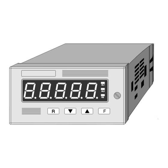
SECTION 3 INSTRUMENT CONFIGURATION 3.1 FRONT PANEL DESCRIPTION Page 3.1 Dpl-e-3-02C.p65 29/01/99, 12.18... - Page 17 AL 2 Indicator OFF = no alarm condition Indicator ON = alarm condition Indicator OFF = setting by serial communication interface disabled indicator ON = setting by serial communication interface enabled Page 3.2 Dpl-e-3-02C.p65 29/01/99, 12.18...
- Page 18 It is used to scroll back the parameters without to memorize the new values. Used to lock/unlock keyboard for parameter modification Page 3.3 Dpl-e-3-02C.p65 29/01/99, 12.18...
- Page 19 3.2 INSTRUMENT CONFIGURATION For configuration procedure, the internal jumper V2 , mounted on CPU card, must be positioned as follows: V2 = open Fig. 3.1 Page 3.4 Dpl-e-3-02C.p65 29/01/99, 12.18...
- Page 20 Before reassembling the instrument, make sure that all the neces- sary hardware settings are made as detailed below: For input selection, the jumpers must be set as follows For mA inputs For 5 V fs inputs For 10 V fs inputs Page 3.5 Dpl-e-3-02C.p65 29/01/99, 12.18...
- Page 21 For alarms output, J250 and J251 must be setted as follows: Contact AL 1 J250 = 1-2 J250 = 2-3 AL 2 J251= 1-2 J251 = 2-3 Setting Page 3.6 Dpl-e-3-02C.p65 29/01/99, 12.18...
- Page 22 For analog retransmission, set the jumpers J104, J105 and J107 as follows: J107 J104 J105 Voltage output J107 J104 J105 mA output Page 3.7 Dpl-e-3-02C.p65 29/01/99, 12.18...
- Page 23 Once the internal jumper has been positioned as described in Fig. Some parameters may not be shown according to the previous 3.1 proceed as follows: parameters setting. 1. The display will show "DPL" for 2 second, than it will show 1) POWER SUPPLY FREQUENCY "COnF" The display will show : NOTE: at this point it is possible to start the default parameter L.F.
- Page 24 Push the F pushbutton to memorize the new choice and go to the square root extraction is selected, this value must be positive). next parameter. Push the F pushbutton to memorize the new value and go to the next parameter. Page 3.9 Dpl-e-3-02C.p65 29/01/99, 12.18...
- Page 25 Push the F pushbutton to memorize the new choice and go to the OFF = alarm 1 not used. next parameter. Push s or t pushbuttons and set the desired options. Push the F pushbutton to memorize the new configuration and go to the next parameter. Page 3.10 Dpl-e-3-02C.p65 29/01/99, 12.18...
- Page 26 The 0 value disables the serial communication interface and, the next parameter. pushing F pushbutton, the instrument will go to parameter 7. Push the F pushbutton to memorize the new value and go to the next parameter. Page 3.11 Dpl-e-3-02C.p65 29/01/99, 12.18...
- Page 27 8 = 8 bit no parity Using s and t pushbuttons it is possible to select the desired byte format. Push the F pushbutton to memorize the new choice and go to the next parameter. Page 3.12 Dpl-e-3-02C.p65 29/01/99, 12.18...
- Page 28 COnF. next parameter. NOTE: 1) The analog retransmission range is not limited by the selected readout range. 2) It is possible to retransmit a reverse range by setting a LSV value higher than FSV value. Page 3.13 Dpl-e-3-02C.p65 29/01/99, 12.18...
-
Page 29: Preliminary
REMOTE: during this operative mode, the alarms threshold setting and the manual reset of the alarms are possible only by After the configuration procedure, it is possible to make the DPL serial link. operative by setting the internal jumper mounted on CPU (see Fig. - Page 30 Loc = keyboard lock and the instrument returns to normal operation. UnLoc = keyboard unlock NOTE: 1) The alarm threshold modification is limited by minimum and maximum readout 2) Resolution and decimal point as selected for readout range. Page 4.2 Dpl-e-4-02C.p65 29/01/99, 12.18...
- Page 31 The analog and digital retransmissions continue to retransmit the displayed value. This function is operative also when the instrument is in remote mode and it is enabled/disabled by external contact (see paragraph 3.2.3. step 3). Page 4.3 Dpl-e-4-02C.p65 29/01/99, 12.18...
-
Page 32: Dip Switches Location
5.1 DIP SWITCHES LOCATION To start with the calibration procedure, the internal jumper V2, mounted on CPU card, must be open: NOTE: during calibration procedure the serial communication interface will be disabled. V2 = open Fig. 5.1 Page 5.1 Dpl-e-5-02C.p65 29/01/99, 12.19... -
Page 33: General Guide Lines For Calibration
RESOLUTION display show "ON". 1) For current input: 0.2 mA NOTE: Pushing R pushbutton it is possible to go back to the 2) For V input : 100 mV previous parameter without modify the calibration. Page 5.2 Dpl-e-5-02C.p65 29/01/99, 12.19... - Page 34 Before to made an input calibration, it is necessary to be sure that all the necessary hardware settings are made as detailed below: For mA inputs For 5 V fs inputs For 10 V fs inputs Page 5.3 Dpl-e-5-02C.p65 29/01/99, 12.19...
- Page 35 - Analog retransmission maximum range value (20 mA) - Analog retransmission minimum range value (0 V) - Analog retransmission maximum range value (10 V) NOTE: apply only appropriate input signal when calibration or checking code are displayed. Fig. 5.2 Page 5.4 Dpl-e-5-02C.p65 29/01/99, 12.19...
- Page 36 The resulting indication should give "00000" +10 counts. Check the linearity by setting the calibrator to 10.000 mA; the readout must be "12500" +10 counts. c) Push F for the next calibration parameter. Fig. 5.3 Page 5.5 Dpl-e-5-02C.p65 29/01/99, 12.19...
- Page 37 Check the zero calibration by resetting the calibrator to 0.000 V. The resulting indication should give "00000" +10 counts. Check the linearity by setting the calibrator to 2.500 V; the readout must be "12500" +10 counts. c) Push F for the next calibration Fig. 5.4 Page 5.6 Dpl-e-5-02C.p65 29/01/99, 12.19...
- Page 38 Check the linearity by setting the calibrator to 5.000 V; the readout must be "12500" +10 counts. c) Push F for the next calibration parameter Fig. 5.5 NOTE: The minimum value must be calibrated at 50 mA even if the output is 4 - 20 mA. Page 5.7 Dpl-e-5-02C.p65 29/01/99, 12.19...
- Page 39 Jumpers J104, J105 and J107 setting J107 J104 J105 Voltage output J107 J104 J105 mA output Fig. 5.6 Page 5.8 Dpl-e-5-02C.p65 29/01/99, 12.19...
- Page 40 With this last operation the instrument returns at the beginning of the ready for next calibration step. calibration routine. Switch off the instrument and set the dip switch V2 according to para. 4.1. Fig. 5.7 Page 5.9 Dpl-e-5-02C.p65 29/01/99, 12.19...
-
Page 41: Preliminary
During this routine the display will show "L.dAtA". reset After loading routine the instrument will return to the initial status. Alarm 2 action Reverse Alarm 2 masking option disable Alarm 2 filter Alarm 2 hysteresis 0.1 % Page 6.1 Dpl-e-6-02C.p65 29/01/99, 12.19... -
Page 42: Default Calibration Parameters
DEFAULT CALIBRATION PARAMETERS The default calibration parameters allow to verify the correct working of the instrument but they are not calibration parameters. NOTE: After default calibration parameters loading, it is necessary to recalibrate the instrument. Page 6.2 Dpl-e-6-02C.p65 29/01/99, 12.19... -
Page 43: Out Of Range
2) Make sure that the input signal is in accordance with instrument configuration. Otherwise, modify the input configuration (see chapter 3.2). 3) Send back the instrument to your supplier for a check. Page 7.1 Dpl-e-7-02C.p65 29/01/99, 12.19... -
Page 44: Error Descriptions
Incorrect calibration data in EAROM memory. It may appear at instrument switching on in operative mode. The instrument does not start to operate. It remakes this check every 2 seconds. If this error persists, remake the calibration procedure. Page 7.2 Dpl-e-7-02C.p65 29/01/99, 12.19... - Page 45 Go to configuration mode, select a parameter and push F pushbutton. If this error persists, send back the instrument to your supplier. Return in operative mode. If this error persists, send back the instrument to your supplier. Page 7.3 Dpl-e-7-02C.p65 29/01/99, 12.19...
- Page 46 Page 7.4 Dpl-e-7-02C.p65 29/01/99, 12.19...
- Page 47 Page 7.5 Dpl-e-7-02C.p65 29/01/99, 12.19...
- Page 48 A Siebe Group Company Factories Branch Offices Representatives CHINA ITALY BENELUX GERMANY ERO ELECTRONIC S.r.l. ERO ELECTRONIC BENELUX S.A./N.V. ERO ELECTRONIC GmbH MALTA ERO ELECTRONIC (Malta) Limited SOUTH AFRICA BRAZIL ERO ELECTRONIC S.A. UNITED KINGDOM / EIRE ERO ELECTRONIC DO BRASIL...
Need help?
Do you have a question about the DPL and is the answer not in the manual?
Questions and answers