Sign In
Upload
Manuals
Brands
ero electronic Manuals
Measuring Instruments
DPS
ero electronic DPS Manuals
Manuals and User Guides for ero electronic DPS. We have
1
ero electronic DPS manual available for free PDF download: Instruction Manual
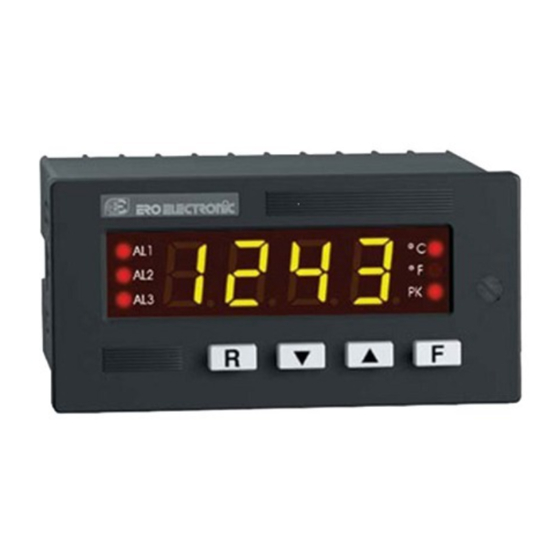
ero electronic DPS Instruction Manual (64 pages)
DIGITAL PANEL INDICATOR
Brand:
ero electronic
| Category:
Measuring Instruments
| Size: 0 MB
Table of Contents
Dimensions and Panel Cut-Out
2
Horizontal Mounting
2
Packing of more Instrument in a Single Cut out
2
Table of Contents
3
Section 1 General Informationsection 1 General Informationsection 5Section 5Section 5Section 5Section 5Instrument Calibrationinstrument Calibrationinstrument Calibrationinstrument Calibrationinstrument Calibration
4
General Specifications
4
Introduction
4
Product Specifications
4
Section 1 General Information
4
Inputs
5
Standard Ranges Table
5
Linear Input
6
RTD (Resistance Temperature Detector)
6
Alarms
7
Additional Functions
7
Options
7
Communication Interface
7
Coding
8
Analog Retransmission
8
Auxiliary Power Supply
8
Labels
9
Identification Label
9
Abridged Labels
9
Instrument Identification Label
9
Section 2Section 2Section 2Section 2Section 2Installationinstallationinstallationinstallationinstallation
11
Installation
11
Mounting
11
How to Insert the Instrument
11
Wiring Guide Lines
12
Rear Terminal
12
Power Line Wiring
12
Power Line
12
Thermocouple Input Wiring
13
Rtd Input Wiring
13
Thermocouple Compensating Cable Colour Codes
14
2-Wire Transmitter Without Power Supply
15
2-Wire Transmitter with Power Supply
15
4-Wire Transmitter with Power Supply
15
External Alarm Reset or Hold Function
17
Local / Remote Operation
17
Alarms Relay Output
17
Alarm 2 Relay Wiring
17
Inductive Loads
18
External Protection for Inductive Load
18
External Loads with very Low Holding Current
19
E.2 Analog Re-Transmission
19
Analog Re-Transmission Wiring
19
Serial Interface
20
Rs-485 Wiring
20
Local/Remote Contact Wiring
21
Section 3Section 3Section 3Section 3Section 3Instrument Configurationinstrument Configurationinstrument Configurationinstrument Configurationinstrument Configuration
23
Instrument Configuration
23
Front Panel Description
23
Indicators
24
Displays
24
Numerical Display
24
Alphanumerical Display
24
Keyboard Description
25
Instrument Configuration
26
Preliminary Hardware Settings
27
Configuration Procedure
30
Parameters List
30
Power Supply Frequency
30
Input Type
30
Tc Type
31
Rtd Type
31
Engineering Unit
31
Burn out
31
Linear Input Type
32
Square Root Extraction
32
Decimal Point Position
32
Initial Scale Readout
32
Break Points Number
33
Input Value of the First Break Point
33
Readout Value of the First Break Point
33
General Note on Linearization by Break Point
33
Digital Filter on Readout Values
34
Frequency Setting
34
External Contact Function
34
Contact Status
34
Analog Retransmission Type
35
Retransmission Minimum Scale Value
35
Retransmission Maximum Scale Value
35
Digital Filter on the Analog Retransmission
35
Serial Interface Address
36
Baud Rate
36
Byte Format
36
Alarm 1 Type
36
Alarm 2
37
Filter on the Alarm Threshold
37
Safety Lock
37
End
37
Operating Instructions
39
Preliminary
39
Operative Mode
39
Peak High and Peak Low Visualization
39
Manual Reset of the Alarms
40
Alarms Threshold Setting
40
Procedure
40
Hold Function
41
Pushing F Pushbutton the Alarm Threshold will be Shown on
41
Instrument Calibration Procedures
42
Dip Switches Location
42
General Guide Lines for Calibration
43
Calibration Procedure
43
Accuracy
43
Resolution
43
How to Proceed
45
Current Input Minimum Range Value
45
Current Input Maximum Range Valu
45
Current Input Check
45
0 - 5 V Input Minimum Range Value
46
0 - 5 V Input Maximum Range Value
46
0 - 5 V Input Check
46
C 4 - 0 - 10 V Input Minimum Range Value
47
C 5 - 0 - 10 V Input Maximum Range Value
47
0 - 10 V Input Check
47
C 6 - TC, MV INPUT MINIMUM RANGE VALUE
48
C 7 -TC, MV INPUT - MAXIMUM RANGE VALUE
48
Tc Input Check
48
C 8 - Rtd Input Minimum Range Value
49
C 9 - Rtd Input Maximum Range Value
49
C J Cold Junction Compensation
50
Cold Junction Compensation Check
50
C L - Analog Retransmission Minimum Range Value
50
C H - Analog Retransmission Maximum Range Value
51
Default Parameters Setting
53
Default Configuration Parameters
53
Preliminary
53
Default Calibration Parameters
54
Default Operative Parameters
54
Error Messages
55
Out of Range
55
Open Input Circuit
55
Errors
55
Error Descriptions
56
E001
56
E038
56
E039
56
E201
57
E211/E212
57
E213
57
E214/E215
57
E218
58
E238
58
E239
58
E311/E312
58
E401
59
E402
59
E403
59
Dps
61
Advertisement
Advertisement
Related Products
ero electronic DPL
ero electronic MEMOCAL 2000
ero electronic Categories
Controller
Temperature Controller
Measuring Instruments
Touch Panel
Control Systems
More ero electronic Manuals
Login
Sign In
OR
Sign in with Facebook
Sign in with Google
Upload manual
Upload from disk
Upload from URL