Table of Contents
Advertisement
Quick Links
Advertisement
Table of Contents

Related Manuals for Eaton ResistTel IP2/IP154


Summary of Contents for Eaton ResistTel IP2/IP154
- Page 1 FHF BA9710 09/17 V8/V9 Explosion proof and weatherproof VoIP-telephones...
-
Page 2: Table Of Contents
Brand names are used with no guarantee that they may be freely employed. Almost all hardware and software designations in this manual are registered trademarks or should be treated as such. All rights reserved. No part of this manual may be reproduced in any way (print, photocopy, microfilm or by any other means) or processed, duplicated or distributed using electronic systems without explicit approval. - Page 3 Operating Manual ............16 Operating Basics ............16 12.1.1 Adjusting the Volume ............16 22.1.1 Adjusting the Ringer Volume ..........17 32.1.1 Do not disturb ..............17 42.1.1 Different Types of Call Numbers ........18 52.1.1 Input of Characters and Special Characters ....... 18 Operating Modes ............
-
Page 4: Voip Telephone Resisttel Ip2 / Ip152 And Exresisttel Ip2 / Ip154
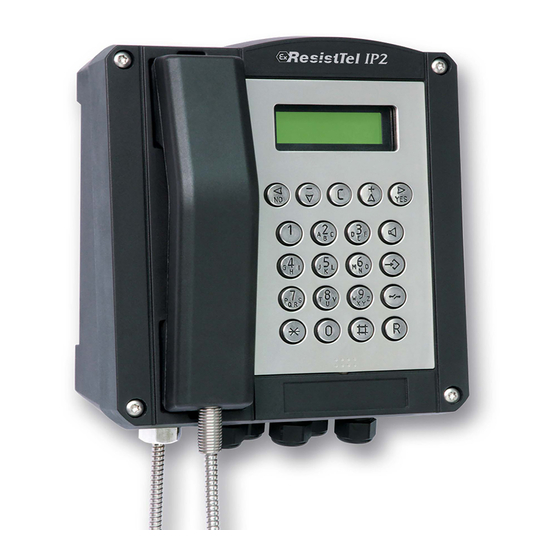
1 VoIP Telephone ResistTel IP2 / IP152 ExResistTel IP2 / IP154 1.1 Keypad Figure 1: Keypad of the VoIP-Telephone... -
Page 5: Keypad Description
1.2 Keypad Description Symbol Description and Key Functions The Loudspeaker key is used to control the hands free and listening mode. The Menu key is used to open the main menu or to save changes. The Disconnect key is used to terminate calls or any menu. The Enquiry key is used to enable the "Hold"... -
Page 6: Display
1.3 Display The displays of the VoIP Telephones ResistTel IP2 / IP152 and ExResistTel IP2 / IP154 have 7 lines with max. 30 characters and a state line for showing information. 1.3.1 Default Display The name and telephone number of the current registration is displayed in the first line. The middle lines display special information relating to the condition. -
Page 7: Menu And Listing Display
Position Symbol Description Name (H.323 or SIP ID or nickname of the PBX configuration) Status line; provides information on the current status of the telephone by means of the following symbols. Date 06.04.10 Time 14:00 No connection to the gatekeeper Connection established to the gatekeeper Connection established to the secondary gatekeeper Connection to the gatekeeper broken. -
Page 8: As-Delivered Condition
Position Symbol Description Menu or listing level 0 < Menu or listing level 1 Menu or listing level 2 Menu or listing level 3 Menu or listing level 4 or lower Display name Scrolling up possible Scrolling up and down possible Scrolling down possible Alphanumerical input Numerical input... -
Page 9: Mounting And Installing
1.5 Mounting and Installing The device must be installed on a plane surface only, in vertical operating position. Loosen the cover screws (2) (see Figure 6 to Figure 8) and detach the upper part of the telephone (1). If the optional accessory headset or a second earpiece is being employed, attach the bracket (10) using two screws (11) to the rear panel of the lower part of the telephone. - Page 10 Figure 6: Set View Figure 7: Inside View of Telephone upper Part...
- Page 11 Figure 8: Inside View of Telephone lower Part X1 X2 X3 X4 10 11 12 13 Figure 9: Connection Diagram with Single LAN Module...
- Page 12 X1 X2 X3 X4 LAN1 LAN2 10 11 12 13 Figure 10: Connection Diagram with Switch LAN Module Connector Description empty Loudspeaker (left) Heater of the Display Illumination of the Display Display LAN Module Keypad Hookswitch (Reed Contact) RS232 Module (optional) Amplifier Module (optional) Handset Relay Module (optional)
-
Page 13: Lan-Connections
1.5.1 LAN-Connections 1.5.1.1 Default Version one LAN Connection with a Cable Gland The telephone has in the default version one internal LAN-connection with a Cable Gland. For the connection a LAN cable must be pulled through the Cable Gland. Inside the phone the female LAN connection from AMP NETCONNECT (TE Connectivity) has to be pressed on the cable (Refer to chapter 1.4 beginning on page 8). -
Page 14: External Power Supply Connection
1.5.2 External Power Supply Connection An external power supply can be adapted to the terminals 5 (+) and 6 (-). The voltage has to be: Without using the optional voltaic separated inputs: 15 V – 57 V DC, 12.95 W With using the optional voltaic separated inputs: 21,5 V –... -
Page 15: Other Terminals
Connector Description Cable to the main board (connection to plug in X12) 1 (relay 1) Idle contact relay 1 2 (relay 1) Base contact relay 1 3 (relay 1) Switching contact relay 1 1 (relay 2) Idle contact relay 2 2 (relay 2) Base contact relay 2 3 (relay 2) -
Page 16: Operating Manual
Operating Manual 2.1 Operating Basics The keys below the display ( ) of the VoIP telephone serve menu navigation and, for edit field input purposes, are assigned an additional function on top of their actual function, as explained below. Key assignment in menu: The function …... -
Page 17: Adjusting The Ringer Volume
Martin vol. 06.04.10 14:40 0:22 Figure 12: Adjusting the Volume You control the volume of the active mode. • At the handset mode you control the volume of the speaker of the handset. • At the listening mode you control the volume of the additional connected speaker of the phone. -
Page 18: Different Types Of Call Numbers
2. To deactivate the do not disturb function again; press the key again for about a second until the signalling in the display is deleted. Afterwards the device will respond to calls in the usual way again. Torsten 06.01.10 14:40 Figure 14: Do not disturb 2.1.4 Different Types of Call Numbers In addition to normal call numbers, your VoIP telephone can also dial H.323 names and... -
Page 19: Operating Modes
2.2 Operating Modes The telephone allows making calls in different operating modes. 1. Handset mode At handset mode the call will be operated with the handset. 2. Handset mode with open listening At handset mode with open listening the call will be operated with the handset. The hands free speaker of the phone will be connected additionally. -
Page 20: Changeover From Handset Mode (With Or Without Open Listening) To Hands Free Mode
2.2.3 Changeover from Handset Mode (with or without Open Listening) to Hands Free Mode To change from handset mode (with or without open listening) to hands free mode, you have to press the loudspeaker key and hang up the handset with pressed loudspeaker . -
Page 21: Call Functions
2.3 Call Functions 2.3.1 Answering Calls You receive a call and your phone rings. The name or phone number of the caller is displayed. The name or phone number of the person for whom the call is intended is also displayed. -
Page 22: Single Dialling
2.3.3.1 Single Dialling For single dialling take the following steps: Torsten 0211654321 Please dial 06.01.10 14:40 0:00 Figure 16: Direct Dialling 1. Respectively to the wanted calling mode: Pick up the handset (handset mode). Press the loudspeaker key (hands free mode). Press the headset key (Key long (longer than a second) and then the loudspeaker key... -
Page 23: Menu Parameter Input Indirect Dialling
b. Press the loudspeaker key (hands free mode). c. Press the headset key (Key long (longer than a second) and then the loudspeaker key ) (headset mode). d. Press the key or key (short or long). With a configured headset you will reach the headset mode otherwise the hands free mode. -
Page 24: Dialling During Existing Connections
2.3.3.3 Dialling during existing Connections During existing connections all entered digits (0 – 9, *, #) are transmitted as DTMF signals. Using this DTMF procedure it is possible to access menu-controlled services (e. g. answering machines, voice boxes) directly via the telephone keypad. 2.3.4 Redialling Up to 100 of the last numbers dialled are saved automatically, together with the time and date, and can be dialled again. -
Page 25: Call Back
d. Press key (short or long) or the key . With a configured headset you will reach the headset mode otherwise the hands free mode. 2.3.5 Call Back Up to 100 of the last incoming calls are saved automatically, together with the time and date, and can be called back, if the number of the caller was transmitted. -
Page 26: Muting
2.3.6 Muting You can mute the microphone during a call to make a confidential enquiry in the room without being heard on the phone. Torsten Thomas 06.01.10 14:40 0:22 Figure 20: Muting Press the key during a call for more than a second. The microphone symbol " " flashes (see Figure 20). -
Page 27: Switching
2.3.8 Switching You can switch between two connections using the switch function. Torsten Peter Torsten Thomas 06.01.10 14:40 0:22 Figure 22: Switching 1. Press the key (short) two times or the key (short) followed by the key during a call with an active line and a line on hold. The active line is put on hold and the line on hold is activated (see Figure 22). -
Page 28: Transferring A Call Directly
d. Press the key (short) followed by the key . The caller will be connected with the dialled number. When transferring a call, you do not have to wait until the desired subscriber answers. You can hang up immediately after dialling the phone number. 2.3.10 Transferring a Call directly You are making a call and want to switch it to another connection. - Page 29 1. Press the key or the key (short) followed by the key during a call with an active line and a line on hold. A conference is set up between the active line and the line on hold. All the subscribers can now talk with each other (see Figure 25).
-
Page 30: Technical Data Weatherproof Telephones
3 Technical Data weatherproof Telephones Hardware-ID Connection data Power supply Power over Ethernet refer to IEEE 802.3af or external power supply Voltage PoE 48V DC (Min. 44V, Max. 57V) Class 0 Voltage external power supply without 15 V – 57 V DC using the optional voltaic separated inputs Voltage external power supply for using... -
Page 31: Ce Symbol
3.1 CE symbol We hereby declare this product is in compliance with the Essential Health and Safety Requirements of EMC Directive 2014/30/EU, Low Voltage Directive 2014/35/EU and RoHS Directive 2011/65/EU. The appropriate standards, technical regulations und specifications you can take from the attached conformity declaration and the conformity declarations on our Website 3.2 Use in marine and offshore segments The telephone ResistTel IP2 is certified by DNV-GL for use in the marine and offshore... - Page 32 Funke + Huster Fernsig GmbH — Gewerbeallee 15-19 — D-45478 Mülheim an der Ruhr — Germany Phone +49 - 208 - 82 68 - 0 — Fax +49 - 208 - 82 68 - 286 — Mail info@fhf.de — www.fhf.de Orders: fhf-orders@eaton.com — Requests: fhf-sales@eaton.com — Support: fhf-support@eaton.com Eaton’s Crouse-Hinds Business Eaton is a registered trademark.
Need help?
Do you have a question about the ResistTel IP2/IP154 and is the answer not in the manual?
Questions and answers