Table of Contents
Advertisement
Quick Links
MS2681A/MS2683A/MS2687A/MS2687B
Spectrum Analyzer
Operation Manual
Vol. 1
(Basic Operating Instructions)
17th Edition
For safety and warning information, please read this
manual before attempting to use the equipment.
Keep this manual with the equipment.
ANRITSU CORPORATION
i
Document No.: M-W1754AE-17.0
Advertisement
Chapters
Table of Contents

Related Manuals for Anritsu MS2681A


Summary of Contents for Anritsu MS2681A
- Page 1 MS2681A/MS2683A/MS2687A/MS2687B Spectrum Analyzer Operation Manual Vol. 1 (Basic Operating Instructions) 17th Edition For safety and warning information, please read this manual before attempting to use the equipment. Keep this manual with the equipment. ANRITSU CORPORATION Document No.: M-W1754AE-17.0...
- Page 2 Insure that you clearly understand the meanings of the symbols BEFORE using the equipment. Some or all of the following five symbols may not be used on all Anritsu equipment. In addition, there may be other labels attached to products which are not shown in the diagrams in this manual.
- Page 3 For Safety WARNING 1. ALWAYS refer to the operation manual when working near locations at which the alert mark shown on the left is attached. If the operation, etc., is performed without heeding the advice in the operation manual, there is a risk of personal injury.
- Page 4 5. The performance-guarantee seal verifies the integrity of the equipment. Calibration To ensure the continued integrity of the equipment, only Anritsu service personnel, or service personnel of an Anritsu sales representative, should break this seal to repair or calibrate the equipment. If the perfor- mance-guarantee seal is broken by you or a third party, the perfor- mance of the equipment cannot be guaranteed.
- Page 5 +30 dBm (RF ATT ≥10 dB) RF Input NEVER input a over maximum ratings to RF Input, excessive power may damage the internal circuits. N MS2681A/MS2683A (plus opt.08 pre-amplifier ON) Maximum AC power (continuous wave) ratings: +10 dBm (RF ATT ≥10 dB) RF Input NEVER input a over maximum ratings to RF Input, excessive power may damage the internal circuits.
- Page 6 Back-up Battery Lithium Battery. This battery should only be replaced by a battery of the same type; since replacement can only be made by Anritsu, contact the nearest Anritsu representative when replacement is required. Note: The battery used in this equipment has a maximum useful life of 7 years.
- Page 7 In addition, this warranty is valid only for the original equipment purchaser. It is not transferable if the equipment is resold. Anritsu Corporation will not accept liability for equipment faults due to unforeseen and unusual circumstances, nor for faults due to mishandling by the customer.
- Page 8 Notes On Export Management This product and its manuals may require an Export License/Approval by the Government of the product's country of origin for re-export from your country. Before re-exporting the product or manuals, please contact us to confirm whether they are export-controlled items or not. When you dispose of export-controlled items, the products/manuals are needed to be broken/shredded so as not to be unlawfully used for military purpose.
- Page 9 2002/96/EC (the "WEEE Directive") in European Union. For Products placed on the EU market after August 13, 2005, please contact your local Anritsu representative at the end of the product's useful life to arrange disposal in ac- cordance with your initial contract and the local law.
- Page 10 Front Panel Power Switch To prevent malfunction caused by accidental touching, the front power switch of this equipment turns on the power if it is pressed continuously for about one second in the standby state. If the switch is pressed continu- ously for one second in the power-on state, the equipment enters the standby state.
- Page 11 ABOUT DETECTION MODE This instrument is a spectrum analyzer which uses a digital storage system. The spectrum analyzer makes level measurements in frequency steps obtained by dividing the frequency span by the number of measure- ment data points (501). This method of measurement cannot detect the signal peak level if the spectrum of a received signal is narrower than these frequency steps.
- Page 12 CE Conformity marking Anritsu affixes the CE Conformity marking on the following product(s) in accordance with the Council Directive 93/68/EEC to indicate that they conform with the EMC and LVD directive of the European Union (EU). CE Marking 1. Product Model...
- Page 13 3. Applied Standards • EMC: Emission: EN 61326: 1997 + A1: 1998 + A2: 2001 + A3: 2003 (Class A) Immunity: EN 61326: 1997 + A1: 1998 + A2: 2001 + A3: 2003 (Annex A) Performance Criteria* IEC 61000-4-2 (ESD) IEC 61000-4-3 (EMF) IEC 61000-4-4 (Burst) IEC 61000-4-5 (Surge)
- Page 14 C-tick Conformity marking Anritsu affixes the C-tick marking on the following product(s) in accordance with the regulation to indicate that they conform with the EMC framework of Australia/New Zealand. C-tick marking N274 1. Product Model Model: MS2681A/MS2683A/MS2687A/MS2687B Spectrum Analyzer Software:...
- Page 15 Power Line Fuse Protection For safety, Anritsu products have either one or two fuses in the AC power lines as requested by the customer when ordering. Single fuse: A fuse is inserted in one of the AC power lines. Double fuse:...
-
Page 17: About This Manual
About This Manual (1) Composition of MS2681A/MS2683A/MS2687A/MS2687B Spectrum Analyzer Operation Manuals The MS2681A/MS2683A/MS2687A/MS2687B Spectrum Analyzer operation manu- als of the standard type are composed of the following three documents. Use them properly according to the usage purpose. Basic operating instruction part Vol. -
Page 18: Table Of Contents
Table of Contents For Safety ............About This Manual........Section 1 General......... Product Outline ............... Composition of Operation Manual .......... Equipment Configuration ............Optional Accessories and Peripherals ........Specifications ................Section 2 Preparations Before Use .... Installation Site and Environmental Conditions ....... Safety Measures .............. - Page 19 Section 5 Basic Operation Procedure..Signal Display ................. Marker Operation ..............“Measure” Function Check ............Shifting of result position ............Screen Hard Copy ..............5-10 Section 6 Performance Test......Requirement for Performance Test ......... Instruments Required for Performance Test ......Performance Test ..............
-
Page 21: Section 1 General
Section 1 General Section 1 General This section outlines the MS2681A/MS2683A/MS2687A/MS2687B Spectrum Ana- lyzer and explains the composition of this manual, the configuration of the MS2681A/ MS2683A/MS2687A/MS2687B standard accessories, the options, the optional accesso- ries, and peripherals for expanding the MS2681A/MS2683A/MS2687A/MS2687B ca- pabilities, and the MS2681A/MS2683A/MS2687A/MS2687B specifications. - Page 22 Section 1 General...
-
Page 23: Product Outline
This unit adopts the synthesizer local system and covers a frequency range of 9 kHz to 3.0 GHz (MS2681A), 9 kHz to 7.8 GHz (MS2683A), and 9 kHz to 30.0 GHz (MS2687A/MS2687B). -
Page 24: Composition Of Operation Manual
Section 1 General Composition of Operation Manual This Operation Manual is composed of 7 sections and appendixes A, B and C. The profile of each section is shown below. Section composition Explanation Section 1 Product outline, standard configuration, options, applicable parts, peripheral General devices, and specifications Section 2... -
Page 25: Equipment Configuration
This paragraph describes the configuration of the MS2681A/MS2683A/MS2687A/MS2687B Spectrum Analyzer with standard accessories and the various options to expand the functions. Standard configuration The table below shows the configuration of the MS2681A/MS2683A/MS2687A/MS2687B Spectrum Analyzer with the standard accessories. Standard Composition Item Model/Order NO. -
Page 26: Options
Section 1 General Options The table below shows the options for MS2681A/MS2683A/MS2687A/MS2687B which are sold separately. Model † - Order No. † Name Remarks Aging Rate: ≤5 × 10 MS2681A-01/MS2683A-01/ Precision frequency reference –10 /day MS2687A-01/MS2687B-01 oscillator MS2681A-02/MS2683A-02/ Narrow resolution bandwidths... -
Page 27: Optional Accessories And Peripherals
Section 1 General Optional Accessories and Peripherals The following table shows the optional accessories and peripherals for MS2681A/MS2683A/MS2687A/ MS2687B which are all sold separately. Optional Accessories Model † - Order No. † Name Remarks J0561 Coaxial cord, 1 m N-P-5W · 5D-2W · N-P-5W... -
Page 28: Specifications
Except were noted otherwise, specified values were obtained after warming up the equipment for 30 minutes at a constant ambient temperature and then performing calibration. The typical values are given for reference, and are not guaranteed. Model MS2681A Frequency range 9 kHz to 3.0 GHz Setting frequency... - Page 29 Section 1 General (Continued) Model MS2681A Frequency response Referred to 50 MHz frequency, input attenuator 10 dB, temperature 18 to 28˚C ±0.6 dB (9 kHz to 3.0 GHz) Referred to 50 MHz frequency,input attenuator 10 to 62 dB ±1.0 dB (9 kHz to 3.0 GHz)
- Page 30 Section 1 General (Continued) Model MS2681A Numbers of point 501,1001 points Detection mode Normal, Positive Peak, Negative Peak, Sample, Average Normal: Simulataneously displays max. and min. points between sample points Positive Peak: Displays max. points between sample points Negative Peak: Displays min. points between sample points...
- Page 31 Section 1 General (Continued) Model MS2681A Video Output Analog RGB Connector: D-Sub 15 pins, jack External reference BNC connector Frequency: 10 MHz ±10 Hz,13 MHz ±13 Hz signal input Level: ≥0 dBm (50 Ω termination) Buffered Output BNC connector Frequency: 10 MHz Output level: p-p: 2 to 5 V (200 Ω...
- Page 32 Section 1 General Model MS2683A Frequency range 9 kHz to 7.8 GHz Frequency band Band 0 (9 kHz to 3.2 GHz), Band 1–L: 1.6 to 3.2 GHz (Option 03), Band1– (3.15 to 6.3 GHz), Band 1 + (6.2 to 7.8 GHz) Pre-selector range 3.15 to 7.8 GHz (Band 1–, 1+) Option 03: 1.6 to 7.8 GHz (Band 1–L, 1–, 1+) 0 Hz to 7.8 GHz...
- Page 33 Section 1 General (Continued) Model MS2683A Referred to 50 MHz frequency, input attenuator 10 dB, temperature 18 to 28˚C ±0.6 dB (9 kHz to 3.2 GHz, Band 0) ±1.0 dB (3.15 to 7.8 GHz, Band 1) Frequency response Referred to 50 MHz frequency, input attenuator 10 to 62 dB ±1.0 dB (9 kHz to 3.2 GHz, Band 0) ±2.0 dB (3.15 to 7.8 GHz, Band 1) After executing pre-select tuning Scale: 10 div...
- Page 34 Section 1 General (Continued) Model MS2683A Numbers of point 501, 1001 Normal: Simultaneously displays max. and min. points between sample points Positive Peak: Displays max. points between sample points Detection mode Negative Peak: Displays min. points between sample points Sample: Displays momentary value at sample points Average: Displays average value between sample points Display function Trace A, Trace B, Trace Time, Trace A/B, Trace A/BG, Trace A/Time...
- Page 35 Section 1 General (Continued) Model MS2683A BNC connector External reference Frequency: 10 MHz ±10 Hz, 13 MHz ±13 Hz signal input Level: ≥ 0 dBm (50 Ω termination) BNC connector Buffered Output Frequency: 10 MHz Output level: p-p: 2 to 5 V (200 Ω termination) BNC connector Output level: 0 to 10 V ±1 V Sweep Output (X)
- Page 36 Section 1 General Model MS2687A Frequency range 9 kHz to 30.0 GHz Frequency band Band 0 (9 kHz to 3.2 GHz), Band 1 – (3.15 to 6.3 GHz), Band 1 + (6.2 to 7.9 GHz), Band 2 + (7.8 to 15.2 GHz), Band 3 + (15.1 to 22.5 GHz), Band 4 + (22.4 to 30 GHz) Pre-selector range 3.15 to 30 GHz (Band 1–, 1+, 2+, 3+, 4+)
- Page 37 Section 1 General Model MS2687A Reference level Reference level accuracy: ±0.5 dB (–49.9 to 0 dBm), ±0.75 dB (–69.9 to –50 dBm, 0.1 to +30 dBm), ±1.5 dB (–80 to –70 dBm) * After calibration, At 50 MHz Frequency, Span1 MHz (when input attenuator, resolution bandwidth, video bandwidth, and sweep time set to AUTO) Resolution bandwidth switching uncertainly: ±0.3 dB (300 Hz to 5 MHz), ±0.5 dB (10 MHz, 20 MHz)
- Page 38 Section 1 General Model MS2687A Sweep time Setting range: 10 ms to 1000 s (manual settable, or automatically settable according to span, resolution bandwidth, video bandwidth) Setting resolution: 5 ms (5 ms to 1 s), most significant 3-digits (≥1 s) Accuracy: ±3% Sweep mode Continuous, single...
- Page 39 Section 1 General Model MS2687A frequency frequency range 18 to 110 GHz Frequency band Band Frequency range Mixer harmonic degree [N] Composition 18 to 26.5 GHz 26.5 to 40 GHz 33 to 50 GHz 40 to 60 GHz 9 or 10 50 to 75 GHz 11 or 12 60 to 90 GHz...
- Page 40 Section 1 General Model MS2687A Video Output Analog RGB connector: D-Sub 15 pins, jack External reference BNC connector Frequency: 10 MHz ± 10 Hz, 13 MHz ± 13 Hz input Level: ≥0 dBm (50 Ω termination) Buffered Output BNC connector Frequency: 10 MHz Output level: p-p: 2 to 5 V (200 Ω...
- Page 41 Section 1 General Model MS2687B Frequency range 9 kHz to 30.0 GHz Frequency band Band 0 (9 kHz to 3.2 GHz), Band 1 – (3.15 to 6.3 GHz), Band 1 + (6.2 to 7.9 GHz), Band 2 + (7.8 to 15.3 GHz), Band 4 + (15.2 to 30 GHz) Pre-selector range 3.15 to 30 GHz (Band 1–, 1+, 2+, 4+) Frequency setting range...
- Page 42 Section 1 General Model MS2687B Reference level Reference level accuracy: ±0.5 dB (–49.9 to 0 dBm), ±0.75 dB (–69.9 to –50 dBm, 0.1 to +30 dBm), ±1.5 dB (–80 to –70 dBm) * After calibration, At 50 MHz Frequency, Span1 MHz (when input attenuator, resolution bandwidth, video bandwidth, and sweep time set to AUTO) Resolution bandwidth switching uncertainly: ±0.3 dB (300 Hz to 5 MHz), ±0.5 dB (10 MHz, 20 MHz)
- Page 43 Section 1 General Model MS2687B Sweep time Setting range: 10 ms to 1000 s (manual settable, or automatically settable according to span, resolution bandwidth, video bandwidth) Setting resolution: 5 ms (10 ms to 1 s), most significant 3-digits (≥1 s) Accuracy: ±3% Sweep mode Continuous, single...
- Page 44 Section 1 General Model MS2687B frequency frequency range 18 to 110 GHz Frequency band Band Frequency range Mixer harmonic degree [N] Composition 18 to 26.5 GHz 26.5 to 40 GHz 33 to 50 GHz 40 to 60 GHz 9 or 10 50 to 75 GHz 11 or 12 60 to 90 GHz...
- Page 45 Section 1 General Model MS2687B Video Output Analog RGB connector: D-Sub 15 pins, jack External reference BNC connector Frequency: 10 MHz ± 10 Hz, 13 MHz ± 13 Hz input Level: ≥0 dBm (50 Ω termination) Buffered Output BNC connector Frequency: 10 MHz Output level: p-p: 2 to 5 V (200 Ω...
- Page 46 Minimum span setting: 100 Hz Average noise level At Input attenuator: 0 dB, RBW: 1 Hz, Detection mode: Sample MS2681A [without Option 08 Pre-amplifier] ≤–146.5 dBm+f [GHz] dB Typ. (1 MHz to 2.5 GHz) ≤–142.5 dBm+f [GHz] dB Typ. (2.5 to 3.0 GHz) [with Option08 Pre-amplifier, when Pre-amplifier Off] ≤–144.5 dBm + 1.5 ×...
- Page 47 Setting Range: Minimum 1 kHz Average noise level At Input RF attenuator: 0 dB, RBW: 10 Hz, Detection mode: Sample MS2681A [without Option 08 Pre-amplifier] ≤ –136.5 dBm + f [GHz] dB Typ. (1 MHz to 2.5 GHz) ≤–132.5 dBm + f [GHz] dB Typ. (2.5 to 3.0 GHz) [with Option 08 Pre-amplifier, when Pre-amplifier Off] ≤–134.5 dBm + 1.5 ×...
- Page 48 • Option 09: Ethernet interface Function Controlled by the external computer Connector 10 base-T • Option 17: I/Q Balanced input* [MS2681A/MS2683A] Connector 1 MΩ (shunt capacitance <100 pF) or 50 Ω, selectable Impedance Input level Differential voltage: 0.1 to 1 V (p-p) Common-mode voltage: ±2.5 V...
- Page 49 Section 1 General • Option 18: I/Q Unbalanced input* Connector 1 MΩ (shunt capacitance <100 pF) or 50 Ω, selectable Impedance Input level 0.1 to 1 V (p-p) AC/DC coupling, switchable * This function is available with the measurement software, sold separately. •...
- Page 50 Section 1 General • Option 22: 13 GHz Low Noise [Only MS2687A] Outline Average noise level of a frequency of 7.9 GHz or more is improved. The following items are separately specified to standard model. Frequency band composition Band Frequency range Mixer Harmonic Degree [N] LO Harmonic Degree (n) 9 kHz to 3.2 GHz...
- Page 51 Section 1 General • Option 34: Lo Output at 4 GHz Frequency 4 GHz ±(4 GHz × reference frequency accuracy) ±1 Hz Frequency accuracy Output level –10 dBm typ. ≤–40 dBc typ. Sprious • Option 46: Auto power recovery Outline Cancels the power switch on front panel and automatically recovers to power-on after power failure.
- Page 52 Section 1 General 1-32.
-
Page 53: Section 2 Preparations Before Use
Section 2 Preparations Before Use This section explains the preparations and safety procedures that should be performed before using the MS2681A/MS2683A/MS2687A/MS2687B Spectrum Analyzer. The safety procedures are to prevent the risk of injury to the operator and damage to the equipment. - Page 54 Section 2 Preparations Before Use...
-
Page 55: Installation Site And Environmental Conditions
CAUTION If the MS2681A/MS2683A/MS2687A/MS2687B Spectrum Analyzer is used at normal tem- peratures after it has been used or stored for a long time at low temperatures, there is a risk of short-circuiting caused by condensation. -
Page 56: Safety Measures
In addition, it is essential to check the power supply voltage. If an abnormal volt- age that exceeds the specified value is input, there is accidental risk of damage to this MS2681A/MS2683A/MS2687A/MS2687B Spec- trum Analyzer and fire. • During power-on... -
Page 57: Input Level To Rf Input
Connector of RF Input MS2681A: MS2683A: MS2687A/MS2687B: CAUTION In case of MS2681A/MS2683A/MS2687A/MS2687B, when you connect N type connector to RF Input, use the coaxial adaptor 34 AKNF50 (K·P-N·J) (sold separately). -
Page 58: Installation
Section 2 Preparations Before Use Installation Rack mounting The Option 47 or Option 48 Rack Mount (sold separately) is required to mount this unit in a rack. The installation method is included in the rack mount kit diagram. -
Page 59: Preparations Before Power-On
Disassembly, adjustment, maintenance, or other access inside this instrument by unqualified personal should be avoided. Maintenance of this instrument should be performed only by Anritsu trained service personnel who are familiar with the risk involved of fire and electric shock. Potentially lethal voltages existing inside this instrument, if contacted accidentally, may result in personal injury or death, or in the possibility of damage to precision components. -
Page 60: Connecting The Power Cord
Section 2 Preparations Before Use Connecting the Power Cord Check that the main [Line] on the rear panel is turned off. Insert the power plug into an outlet, and connect the other end to the power inlet on the rear panel. To ensure that the instrument is grounded, always use the supplied 3-pin power cord, and insert the plug into an outlet with a ground terminal. -
Page 61: Replacing Fuse
In addition, if the AC power supply voltage is unsuitable, there is a risk of the internal circuits of the MS2681A/MS2683A/MS2687A/MS2687B Spectrum Analyzer being damaged by the abnormal voltage. Before supplying power again after changing the fuses, check that the protective grounding described previously is still connected, and check that the AC power supply voltage is suitable. - Page 62 Section 2 Preparations Before Use This unit with standard accessories has a spare 6.3 A fuse. The fuse is mounted in the fuse holder and must be replaced if they blow. Before replacing the blown fuse, locate and remedy the cause . After performing the safety procedures described on the preceding page, replace the fuse according to the following procedure: Step...
-
Page 63: Precaution For Handling Memory Card
• The memory card may be damaged if static electricity is applied to it. Therefore, it is recommended that you make a back up of the memory card. Anritsu accepts no liability for the loss of data on the memory card. • Installing Memory Card Install the memory card to this instrument, with the cutout of the card at the position as shown below. - Page 64 Section 2 Preparations Before Use • Confirmed Memory Card <ATA Card> Manufacturer Model number EPSON SEATA-10M SEATA-20M FUJISOKU JT12MA-BD JT20MA-BD JT32MA-BD JT40MA-BD <Compact Flash Card> Manufacturer Model number SanDisk SDCFB-32-801 SDCFB-64-801 SDCFB-128-801 SDCFB-256-801 SDCFB-64-J60 SDCFB-128-J60 HAGIWARA HPC-CF32V HPC-CF64V HPC-CF128V HPC-CF256V HPC-CF128ZP IO Data CFS-128MX...
-
Page 65: Section 3 Panel Description
Section 3 Panel Description Section 3 Panel Description In this section, the front and rear panels are described assuming the case in which all the options are attached to. Table of Front and Rear Panel Features ...... - Page 66 Section 3 Panel Description...
-
Page 67: Table Of Front And Rear Panel Features
This is a 17 cm (6.5” Type) color TFT liquid crystal display (LCD). It displays the trace waveforms, the parameter settings, the values of marker, and the soft menu keys, etc. Spectrum This sets the MS2681A/MS2683A/MS2687A/MS2687B to a normal spectrum analyzer mode. Signal Analysis This sets the MS2681A/MS2683A/MS2687A/MS2687B to the signal analysis mode in which the measurement software operates. - Page 68 Section 3 Panel Description Panel Marking Explanation of Function Single This sets the sweep mode. [Single] Executes single sweep. [Continuous] Executes continuous sweeping. Press this key after pressing the [Shift] key. The initial default is continuous sweeping. Recall This executes recall/save. [Recall] Reads measurement parameters and waveform data from internal memory or memory card.
- Page 69 Section 3 Panel Description Panel Marking Explanation of Function Entry These keys set the numeric data, units and special functions. [Rotary knob] Used for moving marker and inputting data. ∨ [ ∨ , ] Increments and decrements input data. [Shift] To execute panel functions indicated by blue letters, press this key and then press the blue-lettered key.
- Page 70 This is the RS-232C connector. Connect it to an external system control- ler. Name plate This shows a production number and options. Ethernet This is the 10 base-T connector for Ethernet, and it connects the MS2681A/MS2683A/MS2687A/MS2687B to the external system con- troller.
-
Page 73: Section 4 Soft-Key Menu
Section 4 Soft-Key Menu Section 4 Soft-Key Menu In this section, soft-key menu functions and its hierarchical system are described using a tree. Soft-key Menu List ............. Spectrum mode Menu Tree ..........Config mode Menu Tree ............ 4-30... - Page 74 Section 4 Soft-Key Menu...
- Page 75 Section 4 Soft-Key Menu In this section, soft-key menu functions and its hierarchical system are described using a tree. Matters to be noted about the tree are shown below. (1) Panel Key indicates a hard key on the front panel. (2) Top menus are the menus at the top level which are displayed on the screen when the panel key is pressed.
-
Page 76: Soft-Key Menu List
Section 4 Soft-Key Menu Soft-key Menu List Menu Menu Tree (page/24) Menu Menu Tree (page/24) E) Expand A) A/B,A/BG F) Freq Count A/Time Frequency ACP Freq Frequency Band ACP Method G) Gate Adj ch Pwr Gate Setup Amplitude GPIB Config 2/2 Anttena F Graph Setup Attenuator... - Page 77 Section 4 Soft-Key Menu Menu Menu Tree (page/24) Menu Menu Tree (page/24) P) Parameter W) Wide IF Peak Search Y) Y-Out Power On Config 1/2 Z) Zero/Cal Pre Ampl Zone Width Preset Preslctr Printer R) RBW Recall Ref Line Ref Step RS232C Config 2/2 S) Save...
-
Page 78: Spectrum Mode Menu Tree
Section 4 Soft-Key Menu Menu Tree ( /24) Spectrum mode Menu Tree Panel Key Top menu Lower menues Menu Tree ( 1 /24) Panel Key Top menu Lower menues Frequency Frequency • Set items related to frequency, including the center frequency, start/stop Center frequency, peak->CF, auto synchronization, and frequency scroll step size, Freq... - Page 79 Section 4 Soft-Key Menu Menu Tree ( /24) Panel Key Top menu Lower menues Frequency (from Page 1/24) Band Frequency Band Auto Band Manual Band 2+ Manual Band 0 Manual Band 3+ Manual Band 1-L Manual Band 4+ Manual Band 1– Manual Band 1+ Return...
- Page 80 Section 4 Soft-Key Menu Menu Tree ( /24) Panel Key Top menu Lower menues Amplitude Amplitude RLV Offset REF LEVEL Units Reference offset Units Level Ref Level Log Scale Ref Level offset Lin Scale offset 0.00dB 10dB/div dBuV 10%/div Correction 5dB/div dBmV 5%/div...
- Page 81 Section 4 Soft-Key Menu Menu Tree ( /24) Panel Key Top menu Lower menues • Set the manual/auto of resolution bandwidth, and auto (RBW, VBW and Manual SWP only) or all auto. Auto Manual Auto • Set Ratio of RBW to Span when RBW is Auto and Ratio Mode is “on”. RB,VB,SWT #1 Sets RBW, VBW, Sweep Time, Atten all to Auto.
- Page 82 Section 4 Soft-Key Menu Menu Tree ( /24) Panel Key Top menu Lower menues Sweep Sweep Time • Set the manual/auto of sweep time, and auto (RBW, VBW and SWT only) Time Sweep Time or all auto. Manual Auto Auto SWT Hi-Lvl-Acc Fast RB,VB,SWT...
- Page 83 Section 4 Soft-Key Menu Menu Tree ( /24) Panel Key Top menu Lower menues • Set the selection of normal/delta/no marker, zone marker width, marker->, Marker Marker marker search mode, display line, marker tracking On/Off, zone sweep On/ Normal Off, etc. Marker #1 Selects whether to search for maximum (Peak) or minimum (Dip) Delta...
- Page 84 Section 4 Soft-Key Menu Menu Tree ( /24) Panel Key Top menu Lower menues Peak Peak Search • Set maximum level search, next peak, next right peak, next left peak, Search Marker->, minimum level search, next minimum level, search level Peak Search resolution, threshold level On/Off, etc.
- Page 85 Section 4 Soft-Key Menu Menu Tree ( /24) Panel Key Top menu Lower menues Peak →cf Peak →RLV Single Continuous Single 4-13...
- Page 86 Section 4 Soft-Key Menu Menu Tree ( /24) Panel Key Top menu Lower menues Measure Measure Freq Count Noise Meas Frequency Count On Meas On Count Noise C/N Ratio Channel Count Off Power CountSetup Result Setup Resolution Position 1kHz return return 100Hz C/N Meas...
- Page 87 Section 4 Soft-Key Menu Menu Tree ( /24) Panel Key Top menu Lower menues Measure Occ BW Occupied Occupied Bandwidth Bandwidth Adj ch pwr Method Burst (Page 13/24) N% of Pwr Avg Power xdB Down Mask N% Ratio 99.00% Time xdB Value Template 25.00 dB...
- Page 88 Section 4 Soft-Key Menu Menu Tree ( /24) Panel Key Top menu Lower menues (Previous Page) Mask Meas Select Line Check Mask-1 Limit 1 Pass/Fail Upper Select Mask-2 Limit 1 Mask Table Lower <Mask Edit Screen> Make Up Mask-3 Limit 2 Upper Move Mask Mask-4...
- Page 89 Section 4 Soft-Key Menu Menu Tree ( /24) Panel Key Top menu Lower menues (from Page 10/24) Template Select Line Check Temp-1 Limit 1 Pass/Fail Upper Temp-2 Limit 1 Select Temp Table Lower <Template Edit Screen> Make Up Temp-3 Limit 2 Upper Move Temp-4...
- Page 90 Section 4 Soft-Key Menu Menu Tree ( /24) Panel Key Top menu Lower menues (Page 10/24) Burst Pwr Execute Start Point Stop Point return 4-18...
- Page 91 Section 4 Soft-Key Menu Menu Tree ( /24) Panel Key Top menu Lower menues Recall Recall Recall Recall from Recall Int.Regstr from Mem Card Display Directory Display /Next Directory /Next Dir Disp Detail Outline Recall Items Recall Items Exit Directory Exit Item View...
- Page 92 Section 4 Soft-Key Menu Menu Tree ( /24) Panel Key Top menu Lower menues • Save trace waveform/parameters to the internal memory or memory card. Save Save Recall Save Select saved media, and display file directories. Int.Regstr Display Directory /Next Exit Directory View...
- Page 93 Section 4 Soft-Key Menu Menu Tree ( /24) Panel Key Top menu Lower menues Trace A,B Storage Trace A Hold Count Storage View Normal Sweep Blank Count Avg Count Cumulative Trace B Averaging View Max Hold Count Blank Endless Overwrite Sweep Avg Mode Min Hold...
- Page 94 Section 4 Soft-Key Menu Menu Tree ( /24) Panel Key Top menu Lower menues A/B,A/BG A/B,A/BG • Simultaneously display two waveforms, namely Trace A and Trace B or Trace A and Trace BG (peripheral spectrum containing Trace A). The large (A<B) display is Main Trace and the small one is Sub Trace;...
- Page 95 Section 4 Soft-Key Menu Menu Tree ( /24) Panel Key Top menu Lower menues Time Trace Time • Set to the zero-span time domain display. Set Time Span, Trigger, Trigger Source, Storage, Detection and FM Monitor On/Off, and select Expand Delay Time 10.0 ms (waveform).
- Page 96 Section 4 Soft-Key Menu Menu Tree ( /24) Panel Key Top menu Lower menues Trigger Trigger Trig Video /Gate Trigger Freerun Trig Level High, Middle, Low Triggered -50dB Wide IF Source Wide If Trig Ext Trigger Trig Level Source High Video -10 to 10V Wide IF...
- Page 97 Section 4 Soft-Key Menu Menu Tree ( /24) Panel Key Top menu Lower menues Option Option Trig/Gate Power Meter Average Power PowerMeter Average (It is used at Meter On Off On Off the time of Averaging MS2687A/B- Count Relative 21/23 loading.) Range Hold Auto Average...
- Page 98 Section 4 Soft-Key Menu Menu Tree ( /24) Panel Key Top menu Lower menues Copy Copy Cont Copy Cont Copy Copy to Printer BMP File Printer Paper Feed BJ-M70 (ESC/P) Stop Print HP815C Printer Set up BMP File Set up return •...
- Page 99 Section 4 Soft-Key Menu Menu Tree ( /24) Panel Key Top menu Lower menues Color Change Clr Color Define Clr Pattern1 Copy from Copy Color Color Ptn from Color Pattern2 Pattern1 Select Item Color BackGround Color Pattern3 Pattern2 Color Color Pattern4 Pattern3 Green...
- Page 100 Section 4 Soft-Key Menu Menu Tree ( /24) Panel Key Top menu Lower menues • Execute calibration. Select an item from All Cal, Level Cal, and Freq Cal. All Cal Level Cal Preslctr Y-Out Freq Cal Auto tune Amplitude 0.5V FFT Cal Manual Polarity...
- Page 101 Section 4 Soft-Key Menu Menu Tree ( /24) Panel Key Top menu Lower menues • Initialize measurement parameters. Select one from All, Sweep, Trace, Level Preset Preset Preset and Freq/Time. Preset Sweep controll Preset Trace Parameters Preset Level Parameters Preset Freq/Time Parameters Local...
-
Page 102: Config Mode Menu Tree
Section 4 Soft-Key Menu MS2681A/MS2683A/MS2687A/MS2687B Config Menu Tree ( /2) Config mode Menu Tree Panel Key Top Menu Lower Menu & Entry MS2681A/MS2683A/MS2687A/MS2687B Config Menu Tree (1 /2) Panel Key Top Menu Lower Menu & Entry Config -Display- [Comment] Title Clock Clock &... - Page 103 Section 4 Soft-Key Menu MS2681A/MS2683A/MS2687A/MS2687B Config Menu Tree ( /2) Panel Key Top Menu Lower Menu & Entry -Copy Control- [Copy To] Printer BMP File To Mem Card [Printer Set up] BJ-M70 (ESC/P) HP815C (HP) [BMP File Set up] Color...
- Page 104 Section 4 Soft-Key Menu MS2681A/MS2683A/MS2687A/MS2687B Config Menu Tree ( /2) Panel Key Top Menu Lower Menu & Entry 4-32...
-
Page 105: Section 5 Basic Operation Procedure
Section 5 Basic Operation Procedure Section 5 Basic Operation Procedure Signal Display ..............Turn the power on ............. Execute automatic calibration ........Set the signal to the center of the screen ....Enlarge and display the signal ........Marker Operation ............... “Measure”... - Page 106 Section 5 Basic Operation Procedure...
-
Page 107: Signal Display
Section 5 Basic Operation Procedure The basic operation procedure of this equipment is Signal display explained here. The operations are listed on the right. 1) Turn the power on, Also, the explanation will advance assuming that a 2) execute automatic calibration, 500 MHz signal is applied to the input connector. -
Page 108: Execute Automatic Calibration
Section 5 Basic Operation Procedure Execute automatic calibration Wait after switching on the power supply of the machine (warm up period) till the internal temperature becomes stable. This period is approximately 10 minutes. After warm up, execute automatic calibration. Press the Shift key then the 0 key. Select All Cal from the menu displayed on the display. -
Page 109: Enlarge And Display The Signal
Section 5 Basic Operation Procedure Hold Press the Shift GHZ key The display of the soft key menu can be switched Hold on/off using the Shift GHZ key. When the menu disappears, the set up parameters are displayed. Fig. 5-4 Press the Frequency key, then use the ten-key pad (numeric keys) to enter 500 MHz. -
Page 110: Marker Operation
Section 5 Basic Operation Procedure Marker Operation Here, check that the signal frequency and level are displayed in a marker display area. The zone marker automatically fetches the highest level signal within the zone and displays the frequency and level. The following items can easily be checked by the soft key menu tab: How many pages of the soft key menu being displayed currently are there?,... - Page 111 Section 5 Basic Operation Procedure Press the Peak Search key. Advanced operation memo: It is convenient that the page can also be turned over by repeatedly pressing the panel key. This method is used when key (s), such as the Measure key, has a number of pages. Besides, the Freq/Ampl and Marker-related keys do not turn over the page by repeatedly pressing the panel key.
-
Page 112: Measure" Function Check
Section 5 Basic Operation Procedure “Measure” Function Check Press the Preset key and the Preset All key in order. Press the Peak Search key. If the zero beat signal level (local feed through) is larger than the signal level and the marker fetches the zero beat level, press the “Next peak”... -
Page 113: Shifting Of Result Position
Section 5 Basic Operation Procedure Shifting of result position Press the Measure key and the Result Position* key in order. User can select a displayed position of measured result from 4 patterns. Displayed position is upper right, upper left, lower right, or lower left. Fig. -
Page 114: Screen Hard Copy
Section 5 Basic Operation Procedure Screen Hard Copy The screen can be hard-copied with the BJ-M70 printer (Canon) via a Centronics interface, and the procedures are described below: As illustrated below, connect the Parallel connector and printer with an attached Parallel cable. Press the Copy key, and the currently displayed screen is hard-copied. -
Page 115: Section 6 Performance Test
Section 6 Performance Test Section 6 Performance Test In this chapter, measuring instruments, setup and operations necessary for conducting performance tests of MS2681A/MS2683A/MS2687A/MS2687B are explained. Requirement for Performance Test ........Instruments Required for Performance Test ...... Performance Test .............. Reference oscillator frequency stability .... - Page 116 Section 6 Performance Test...
-
Page 117: Requirement For Performance Test
Section 6 Performance Test Requirement for Performance Test Performance tests are used as preventive maintenance to prevent degradation of the performance of MS2681A/ MS2683A/MS2687A/MS2687B Spectrum Analyzer (hereinafter, called “this unit”) before it occurs. Use the performance tests whenever necessary such as at acceptance and periodic inspection of this unit and to verify performance after repair. -
Page 118: Instruments Required For Performance Test
Section 6 Performance Test Instruments Required for Performance Test A list of instruments required for performance test is shown below. Instruments Required for Performance Test (1/2) Recommended instrument Test item Required Performance † name (Model name) Frequency standard • Aging Rate Reference oscillator frequency ≤3 ×... - Page 119 Section 6 Performance Test Instruments Required for Performance Test (2/2) Recommended instrument Test item Required Performance † name (Model name) Power meter (ML4803A) • Main instrument accuracy Frequency response ±0.02 dB Reference-level accuracy • Frequency range Input-attenuator switching error 100 kHz to 30 GHz (depending on the power sensor type) Power sensor (MA4701A)
-
Page 120: Performance Test
The warm-up time depends on the test item. For test item other than oscillator frequency, warm-up the equipment for at least thirty minutes and test the performance after the MS2681A/MS2683A/MS2687A/MS2687B series stabilizes completely. Also, begin measurement after taking the warm-up time of the calibration instrument into full consideration. -
Page 121: Reference Oscillator Frequency Stability
Section 6 Performance Test Reference oscillator frequency stability Test the frequency stability of the 10 MHz reference oscillator. Stability is determined by measuring frequency variation after 24 hours and after 48 hours of power on at ambient temperatures of 0°C and 50°C. (1) Specifications I Reference oscillator •... - Page 122 Section 6 Performance Test (4) Procedure Aging rate/day: Test this at the ambient temperature ±2°C in a vibration-free place. Step Procedure Set the change over switch (FREQ STD: INT/EXT) on the MF1601A counter rear panel to EXT. Set the power supply switch on the spectrum analyzer rear panel to On and then the Power switch on the spectrum analyzer front panel to On.
-
Page 123: Frequency Readout Accuracy
As shown in the figure, the Synthesized Signal Generator uses the signal source phase-locked with the same accuracy as the 10 MHz reference oscillator of the spectrum analyzer. (1) Specification [MS2681A/MS2683A] Frequency readout accuracy: ± (readout frequency × reference frequency accuracy + span × span accuracy + resolution bandwidth × 0.15 + 10 Hz) [MS2687A/MS2687B] Frequency readout accuracy: ±... - Page 124 Synthesized signal generator: 69269A • Frequency standard (3) Setup Marker display frequency MKR : 500.0010MHz CF : 500MHz Span : 2kHz Anritsu MS8608A Frequency standard (stability should be 3 × 10 –14 /day or less, and traceable to national standards) Output RF Input Coaxial adaptor (N-P •...
- Page 125 Even if there is not a Frequency standard, simplified measurement can be performed by setting up as shown in the figure below. In this case, the following specification is applied: [MS2681A/MS2683A] ± (span × span accuracy + resolution bandwidth × 0.15 + 10 Hz) [MS2687A/MS2687B] ±...
- Page 126 Section 6 Performance Test (4) Precaution Set the signal generator output level to approximately –10 to –20 dBm. (5) Procedure Step Procedure Press the [Preset] key of this unit. Operate Freq Cal. Set the signal generator output frequency equal to the center frequency (500 MHz) in the following table.
-
Page 127: Frequency Span Readout Accuracy
SG. The frequency difference between the peak levels at the 1st and 9th divisions is equal to the frequency span × 0.8. (1) Specification [MS2681A/MS2683A] Frequency span accuracy: ±1.0% (Single band sweep, data point 1001) [MS2687A] Frequency span accuracy: ±1.0% (band 0, 1), ±2.5% (band 2, 3, 4) - Page 128 Section 6 Performance Test (3) Setup Measure frequency difference with SG 10 MHz STD RF Input Buff Out Coaxial adaptor (N-P • SMA-J) CF : 1.000 000 GHz Span : 1 kHz Synthesized signal generator REF IN RF OUTPUT Coaxial adaptor (SMA connector) Frequency Span Readout Accuracy Test (4) Precaution...
- Page 129 Section 6 Performance Test (5) Procedure Step Procedure Press the [Preset] key. Operate Freq Cal. Connect the 69269A output to the spectrum analyzer RF Input. Set the spectrum analyzer as shown below: Span ............20 kHz Center Freq .......... 1000 MHz Set the 69269A output frequency to the f frequency (999.992 MHz) shown in the table on the next page.
-
Page 130: Resolution Bandwidth (Rbw) And Selectivity
Section 6 Performance Test Resolution bandwidth (RBW) and selectivity If there are two input signals with the frequency difference corresponding to 3 dB bandwidth (of IF final stage), these signals can be resolved as two spectrum waveforms. This is called the resolution bandwidth. Selectivity can be improved by narrowing the 60 dB bandwidth. - Page 131 Section 6 Performance Test (3) Setup 1 dB/ 10 MHz STD RF Input Buff Out Coaxial cable Coaxial cable (BNC connector) (N-type connector) 10 dB/ REF-IN MG3633A OUTPUT 100 MHz Resolution Bandwidth/Selectivity Test 6-17...
- Page 132 Section 6 Performance Test (4) Procedure (a) Resolution bandwidth accuracy Step Procedure Press the [Preset] key. Perform all calibration. Set the spectrum analyzer as shown below: Center Freq ..........100 MHz Span ............1 kHz RBW (MANUAL) ........300 Hz Scale ..........
- Page 133 Section 6 Performance Test Resolution Bandwidth (3 dB) Resolution bandwidth Span frequency 3 dB bandwidth 300 Hz 1 kHz 1 kHz 3 kHz 3 kHz 10 kHz 10 kHz 30 kHz 30 kHz 100 kHz 100 kHz 300 kHz 300 kHz 1 MHz 1 MHz 3 MHz...
- Page 134 Section 6 Performance Test (b) Resolution bandwidth selectivity Step Procedure Set the spectrum analyzer as shown below: Center Freq ..........200 MHz Span ............10 kHz RBW (MANUAL) ........300 Hz Scale ..........LOG 10 dB/div VBW ............100 Hz Marker ..........
- Page 135 Section 6 Performance Test Selectivity Test (60 dB/3 dB Bandwidth Ratio) Setting the spectrum analyzer Measured result Calculated result 3 dB Selectivity Resolution bandwidth Span frequency 60 dB bandwidth (60 dB BW ÷ 3 dB BW) bandwidth 300 Hz 10 kHz 1 kHz 30 kHz 3 kHz...
-
Page 136: Sideband Phase Noise
Section 6 Performance Test Sideband phase noise When the resolution bandwidth is set to a fixed value and a signal that has far less sideband-noise level than the equipment to be tested is input, check the level of the noise as compared to the peak signal (dBc) at the specified frequency away from the peak. - Page 137 Section 6 Performance Test (4) Procedure Step Procedure Press the [Preset] key. Operate All Cal. Set the MG3633A output to 1000 MHz and 0 dBm. Set the spectrum analyzer as shown below: Center Freq ........1.000 010 GHz Span ............25 kHz Reference Level ........
-
Page 138: Frequency Measurement Accuracy
• Resolution: 1 Hz, 10 Hz, 100 Hz, 1 kHz [MS2681A/MS2683A] Accuracy: ≤ (Readout frequency × reference oscillator accuracy ± (1 count) ± 2 Hz) [MS2687A/MS2687B] Accuracy: ≤ (Readout frequency × reference oscillator accuracy ± (1 count) ± 2 Hz × N) (2) Test instrument •... - Page 139 Note: Even if there is not a Frequency standard, simplified test can be performed by setting up as shown in the figure below. In this case, the following specification is applied: [MS2681A/MS2683A] (± 1 count ± 2 Hz) [MS2687A/MS2687B] (± 1 count ± 2 Hz × N)
- Page 140 Section 6 Performance Test (4) Procedure Step Procedure Press the [Preset] key. Set the 69269A to 500 MHz and –10 dBm. Set the spectrum analyzer as shown below: Center Freq ..........500 MHz Span ............5 kHz Press the [Measure] key and set to Frequency Count. Press Setup and set Resolution to 1 Hz. Then, press the Return key and set to Count On.
-
Page 141: Amplitude Display Linearity
Section 6 Performance Test Amplitude display linearity Test the error per vertical graduation for the LOG display. For the LOG display linearity, test that the graduation is equal to the logarithm (dB) of the input signal level. Input the correct level signal to the RF Input via an external attenuator and calculate the error from the attenuation of the attenuator and the ∆... - Page 142 Section 6 Performance Test (4) Procedure LOG display linearity Step Procedure Press the [Preset] key. Operate All Cal. Set the MG3633A to 100 MHz, 0 dBm. Set the MN510C to 0 dB. Set the spectrum analyzer as shown below: Center Freq ..........100 MHz Span ............
- Page 143 Section 6 Performance Test Step Procedure As shown on Fig. (b), read the level of the current marker when ATT is set at 10 dB. An error is determined as calibrated ATT 10 dB value +∆ marker level. Add a marker level corresponding to the calibrated ATT value when ATT is set as 10 to 90 DB (with 10 dB steps) and determine the error.
- Page 144 Section 6 Performance Test Log Display Linearity (10 dB/div) setting Error (dB)=A+B ∆ marker (dB) calibration level (dB) value (dB) 0 (reference) 0 (reference) 0 (reference) ------ ------ ------ ------ ------ ------ ------ ------ ------ ------ ------ ------ ------ ------ ------ ------ ------...
-
Page 145: Frequency Response
Generally, when one or more signals with a different frequency but the same amplitude are input, the spectrum analyzer displays the same amplitude for each spectrum on the screen. (1) Specifications [MS2681A] • Frequency response Referred to 50 MHz, input attenuator = 10 dB, temperature range 18 to 28˚C ±0.6 dB (9 kHz to 3.0 GHz) - Page 146 Section 6 Performance Test [MS2687B] • Relative flatness At input attenuator = 10 dB, refered to center point of maximum deviation movement point and minimum deviation movement point within band. ±1.0 dB (9 kHz to 3.2 GHz, band 0), ±1.5 dB (3.15 to 7.9 GHz, band 1) ±3.0 dB (7.8 to 15.3 GHz, band 2) ±1.5 dB (15.2 to 30.0 GHz, band 4) •...
- Page 147 Section 6 Performance Test (5) Procedure (a) Calibration of signal-generator 69269A Step Procedure Set the 69269A as shown below: OUTPUT FREQ ........50 MHz OUTPUT LEVEL ........–6 dBm Connect the 69269A output to the power sensor input with a coaxial cable. Read the power meter display.
- Page 148 Section 6 Performance Test Frequency Response (Band 0) Frequency Calibration value (dBm) Marker level (dB) Deviation (dB) 50 MHz 0 (reference) 0 (reference) 0 (reference) 200 MHz 500 MHz 1 GHz 1.5 GHz 2 GHz 3 GHz Frequency Response (Band 1-) Frequency Calibration value (dBm) Marker level (dB)
-
Page 149: Reference Level Accuracy
Section 6 Performance Test Reference level accuracy Here the absolute amplitude level at 50 MHz is tested. Confirm the level accuracy after inputting an SG output (calibrated by a standard power meter) to this unit. (1) Specification • Reference level accuracy: At 50 MHz frequency and 1 MHz span after automatic calibration (Resolution bandwidth, video bandwidth, RF ATT and sweep time set to AUTO) ≤... - Page 150 Section 6 Performance Test (4) Precautions 1) Set the resolution bandwidth, video bandwidth, RF ATT and sweep time to Auto. 2) This test should be performed after warming up this instrument for 60 minutes or more. (5) Procedure Step Procedure Press the spectrum analyzer [Preset] key.
- Page 151 Section 6 Performance Test Step Procedure Change the attenuator in 10 dB steps, set the reference level as shown in the table below and read the marker level each time. Reference level Marker Correction factor Error setting readout of ATT 0 dBm –10 dBm –20 dBm...
-
Page 152: Average Noise Level
Average noise level At RBW=300 Hz, VBW = 1 Hz, Detection mode: Sample, input attenuator = 0 dB [MS2681A] ≤–124 dBm + f [GHz] dB (1 MHz to 2.5 GHz, band 0) ≤–120 dBm + f [GHz] dB (2.5 to 3.0 GHz) [MS2683A] ≤–124 dBm + f [GHz] dB (1 MHz to 2.5 GHz, band 0) - Page 153 Section 6 Performance Test (3) Setup RF Input 50 Ω terminator (Terminates RF Input) Average Noise Level Test (4) Procedure Step Procedure Press the [Preset] key of the spectrum analyzer. Operate All Cal. Terminate the RF Input with a 50 Ω terminator. Set the spectrum analyzer as shown below (Time Domain): Band ..............
- Page 154 Section 6 Performance Test Step Procedure The marker reading is the average noise level. Setting the spectrum analyzer Measured result Band Center frequency 1 MHz 99 MHz 499 MHz 999 MHz 1499 MHz 1999 MHz 2499 MHz 2999 MHz 3199 MHz 3201 MHz 3499 MHz 3999 MHz...
-
Page 155: Second Harmonic Distortion
(LPF). (1) Specification • Second harmonic distortion: [MS2681A/MS2683A] At mixer input level –30 dBm: ≤–60 dBc (10 to 200 MHz, Band 0) ≤–75 dBc (0.2 to 0.85 GHz, Band 0) ≤–70 dBc (0.85 to 1.6 GHz, Band 0) At mixer input level –10 dBm:... - Page 156 Section 6 Performance Test (3) Setup Low-pass filter Signal generator MG3633A RF Input RF OUTPUT INPUT OUTPUT Coaxial cable (N connector) Second Harmonic Distortion Test (4) Procedure Step Procedure Press the [Preset] key. Operate All Cal. Connect the LPF VLF-141 (fp=50 MHz) Set the SG output frequency to 48 MHz and the output level to –20 dBm.
- Page 157 Section 6 Performance Test Step Procedure Move the marker to the peak of the spectrum waveform and make the marker the ∆ marker. Set the center frequency to twice the fundamental wave frequency to display the second harmonic on the screen. The ∆...
-
Page 158: Resolution Bandwidth (Rbw) Switching Uncertainty
Section 6 Performance Test Resolution bandwidth (RBW) switching uncertainty When the resolution bandwidth (RBW) is switched, its level error at the peak point is measured. (1) Specification Resolution bandwidth switching uncertainty: ± 0.3 dB (RBW=300 Hz to 5 MHz) • (referenced to RBW: 3 kHz) ±... - Page 159 Section 6 Performance Test (4) Procedure Step Procedure Press the [Preset] key of the spectrum analyzer. Operate All Cal. Set the signal generator MG3633A as shown below. OUTPUT FREQ ........100 MHz OUTPUT LEVEL ........0 dBm Set the spectrum analyzer as shown below. Center Freq ..........
- Page 160 Section 6 Performance Test Resolution bandwidth (RBW) switching uncertainty Setting the spectrum analyzer Measured result ∆ marker readout Resolution bandwidth Frequency span 300 Hz 2 kHz 1 kHz 5 kHz 3 kHz 15 kHz 10 kHz 50 kHz 30 kHz 150 kHz 100 kHz 500 kHz...
-
Page 161: Input Attenuator (Rf Att) Switching Uncertainty
Section 6 Performance Test Input attenuator (RF ATT) switching uncertainty At this point, measure the switching error when the amount of attenuation in the RF input section is switched. When the input attenuator is switched, IF-section step-amplifier gain is switched. To keep this step-amplifier gain constant, the reference level is switched according to the amount of input attenuator attenuation. - Page 162 Section 6 Performance Test (4) Procedure Step Procedure Press the [Preset] key of the spectrum analyzer. Operate All Cal. Set the spectrum analyzer as shown below: Center Freq ..........100 MHz Span ............200 kHz Set the signal generator MG3633A as shown below: OUTPUT FREQ ........
- Page 163 Section 6 Performance Test Setting MS2683A Attenuator Measured result Calculated result Ref Level Input attenuator Setting Correction Marker level Error Deviation –10 dBm 60 dB 0 dB –20 dBm 50 dB 10 dB –30 dBm 40 dB 20 dB –40 dBm 30 dB 30 dB –50 dBm...
-
Page 164: Frequency Domain Sweep Time Accuracy
Section 6 Performance Test Frequency domain sweep time accuracy (1) Specification ±3% (10 msec to 100 sec) • Sweep time accuracy: (2) Test instruments • Signal generator: 69269A • Frequency counter: MF1601A (3) Setup Frequency counter MF1601A INPUTA Coaxial cable (BNC connector) Sweep status (Z) - Page 165 Press the [Preset] key of the spectrum analyzer. Operate All Cal. Connect the Sweep Status (Z) output of spectrum analyzer to Input A of MF1601A. Set the MS2681A/MS2683A/MS2687A/MS2687B spectrum analyzer as shown below: Center Frequency ........300 MHz Span ............2 MHz Ref Level ...........
- Page 166 Press the [Preset] key of the spectrum analyzer. Operate All Cal. Connect the output of 69269A to the spectrum analyzer according to setup figure. Set the MS2681A/MS2683A/MS2687A/MS2687B spectrum analyzer as shown below: Center Frequency ........300 MHz Span ............2 MHz Ref Level ...........
-
Page 167: Time Domain Sweep Time Accuracy
Section 6 Performance Test Time domain sweep time accuracy (1) Specification ±1.0% • Time domain sweep time accuracy: (2) Test instruments • Signal generator: 69269A • Frequency counter: MF1601A (3) Setup Frequency counter MF1601A INPUTA Coaxial cable (BNC connector) Sweep status (Z) Signal generator 69269A... - Page 168 Press the [Preset] key of the spectrum analyzer. Operate All Cal. Connect the Sweep Status (Z) output of spectrum analyzer to Input A of MF1601A. Set the MS2681A/MS2683A/MS2687A/MS2687B spectrum analyzer as shown below: Center Frequency ........300 MHz Span ............0 MHz Ref Level ...........
- Page 169 Section 6 Performance Test Operate All Cal. Connect the output of 69269A to the spectrum analyzer according to setup figure. Set the MS2681A/MS2683A/MS2687A/MS2687B spectrum analyzer as shown below: Center Frequency ........300 MHz Span ............0 MHz Ref Level ........... 0 dBm RBW ............
-
Page 170: Service
Section 6 Performance Test Service If the instrument is damaged or does not operate as specified, contact your nearest Anritsu dealer or business office for repair. When you request repair, provide the following information: (a) Model name and serial number on rear panel... -
Page 171: Section 7 Storage And Transportation
Section 7 Storage and Transportation Section 7 Storage and Transportation This section describes the long-term storage, repacking and transportation of MS2681A/ MS2683A/MS2687A/MS2687B as well as the regular care procedures and the timing. Cleaning Cabinet ............... Storage Precautions ............Precautions before storage ........ - Page 172 Section 7 Storage and Transportation...
-
Page 173: Cleaning Cabinet
Section 7 Storage and Transportation Cleaning Cabinet Always turn the spectrum analyzer POWER switch OFF and disconnect the power plug from the AC power inlet before cleaning the cabinet. To clean the external cabinet: • Use a soft, dry cloth for wiping off. •... -
Page 174: Storage Precautions
Section 7 Storage and Transportation Storage Precautions This paragraph describes the precautions to take for long-term storage of the MS2681A/MS2683A/MS2687A/ MS2687B Spectrum Analyzer. Precautions before storage (1) Before storage, wipe dust, finger-marks, and other dirt off the spectrum analyzer. (2) Avoid storing the spectrum analyzer where: 1) It may be exposed to direct sunlight or high dust levels. -
Page 175: Repacking And Transportation
Section 7 Storage and Transportation Repacking and Transportation The following precautions should be taken if the MS2681A/MS2683A/MS2687A/MS2687B Spectrum Analyzer must be returned to Anritsu Corporation for servicing. Repacking Use the original packing materials. If the spectrum analyzer is packed in other materials, observe the following packing procedure: (1) Wrap the spectrum analyzer in a plastic sheet or similar material. - Page 176 Section 7 Storage and Transportation 7-6.
- Page 177 Appendixes Appendixes Appendix A Front and Rear Panel Layout ......A-1 Appendix B Block Diagram ..........B-1 Appendix C Performance Test Record ......C-1 App-I...
- Page 178 Appendixes App-II.
-
Page 179: Appendix A Front And Rear Panel Layout
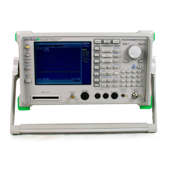
Appendix A Front and Rear Panel Layout Appendix A This appendix shows the front and rear panel layout. Fig. NO. Name Fig. A-1 MS2681A Front Panel Fig. A-2 MS2681A Rear Panel Fig. A-3 MS2683A Front Panel Fig. A-4 MS2683A Rear Panel Fig. - Page 180 Appendix A...
- Page 181 Fig. A-1 MS2681A Front Panel...
- Page 182 Fig. A-2 MS2681A Rear Panel...
- Page 183 Fig. A-3 MS2683A Front Panel...
- Page 184 Fig. A-4 MS2683A Rear Panel...
- Page 185 Fig. A-5 MS2687A Front Panel...
- Page 186 Fig. A-6 MS2687A Rear Panel...
- Page 187 Fig. A-7 MS2687B Front Panel...
- Page 188 Fig. A-8 MS2687B Rear Panel A-10.
-
Page 189: Appendix B Block Diagram
Appendix B Block Diagram Appendix B This appendix shows the Block Diagram of the MS2681A/MS2683A/MS2687A. Fig. NO. Name Fig. B-1 MS2681A Block Diagram Fig. B-5 MS2683A Block Diagram Fig. B-9 MS2687A Block Diagram Fig. B-15 MS2687B Block Diagram... - Page 190 Appendix B...
- Page 198 B-10...
- Page 199 B-11...
- Page 200 B-12...
- Page 201 B-13...
- Page 202 B-14...
- Page 203 B-15...
- Page 204 B-16...
- Page 205 B-17...
- Page 206 B-18.
-
Page 207: Appendix C Performance Test Record
Appendix C Performance Test Record Appendix C MS2681A ability examination result document ....C-3 MS2683A ability examination result document ....C-13 MS2687A ability examination result document ....C-23 MS2687B ability examination result document ....C-35... - Page 208 Appendix C...
- Page 209 Appendix C MS2681A Performance Test Record (1/10) NO. ____________ DATE __________ MS2681A Model ___________________________ Serial NO. ________________________ Options __________________________ Date _____________________________ Tested by ________________________ Ambient temparature _______________ ˚C Relative humidity __________________ % Perwer mains line voltage (nominal) _________ Vac Powermains line frquency (nominal) _________ Hz...
- Page 210 Appendix C (2/10) MS2681A Model Name ______________________ date _______________________ Serial NO. ________________________ Tested by ________________________ Reference oscillator frequency stability • Frequency stability Referred to the frequency after 24 hour warm-up ±2 × 10 –8 Min. Result Max. Cumulative error Frequency stability/day -2×10...
- Page 211 Appendix C (3/10) MS2681A Model Name ______________________ date _______________________ Serial NO. ________________________ Tested by ________________________ Frequency span readout accuracy Single band sweep ±1.0% MS2681A Min. Result Max. Cumulative (Hz) (Hz) (Hz) error (Hz) Center frequency Span frequency 1.5 GHz 20 kHz...
- Page 212 Appendix C (4/10) MS2681A Model Name ______________________ date _______________________ Serial NO. ________________________ Tested by ________________________ Resolution bandwidth accuracy and selectivity • Resolution bandwidth accuracy ±20% (300 Hz to 10 MHz) ±40% (20 MHz) MS2681A Min. Max. Min. Result Max. Resolution...
- Page 213 Appendix C (5/10) MS2681A Model Name ______________________ date _______________________ Serial NO. ________________________ Tested by ________________________ Sideband phase noise ≤–108 dBc/Hz (Frequency: 1 GHz, frequency offset: 10 kHz) ≤–120 dBc/Hz (Frequency: 1 GHz, frequency offset: 100 kHz) MS2683A Frequency offset Result...
- Page 214 Appendix C (6/10) MS2681A Model Name ______________________ date _______________________ Serial NO. ________________________ Tested by ________________________ Frequency response Referred to 50 MHz, RF ATT10 dB, Temperature18 to 28˚C ±0.6 dB (9 kHz to 3.0 GHz) Calculated Cumulative MS2681A Correction (dB) Result (dB) Spec.
- Page 215 Resolution bandwidth: 300 Hz, VBW: 1 Hz, Input attenuator: 0 dB ≤–124 dBm + f [GHz] dB (1 MHz to 2.5 GHz, Band 0) ≤–120 dBm + f [GHz] dB (2.5 to 3.0 GHz, Band 0) MS2681A setting Cumulative error Result (dB) Spec.(dBm)
- Page 216 Second harmonic distortion Mixer input level: –30 dBm ≤–60 dBc (Frequency: 10 to 200 MHz) ≤–75 dBc (Frequency: 0.2 to 0.85 GHz) ≤–70 dBc (Frequency: 0.85 to 1.5 GHz) Signal generator MS2681A setting Cumulative error Result (dB) Spec.(dBc) Output frequency Band (dB) ±1.09...
- Page 217 Serial NO. ________________________ Tested by ________________________ Input attenuator (RF ATT) switching error Referred to 50 MHz, RF ATT 10 dB ±0.3 dB (10 to 50 dB) ±0.5 dB (52 to 62 dB) MS2681A setting Attenuator Result (dB) Calculated Cumulative Spec.(dB)
- Page 218 Appendix C (10/10) MS2681A Model Name ______________________ date _______________________ Serial NO. ________________________ Tested by ________________________ Time domain sweep time accuracy ±1% (10 µs to 1000 s) MS2681A setting Min. Result Max. Spec. Cumulative error Sweep time ±1% ±11 ns 100 ms...
- Page 219 Appendix C MS2683A Performance Test Record (1/10) NO. ____________ DATE __________ MS2683A Model ___________________________ Serial NO. ________________________ Options __________________________ Date _____________________________ Tested by ________________________ Ambient temparature _______________ ˚C Relative humidity __________________ % Perwer mains line voltage (nominal) _________ Vac Powermains line frquency (nominal) _________ Hz Test Equipment used Descriptions MODEL NO.
- Page 220 Appendix C (2/10) MS2683A Model Name ______________________ date _______________________ Serial NO. ________________________ Tested by ________________________ Reference oscillator frequency stability • Frequency stability Referred to the frequency after 24 hour warm-up ±2 × 10 –8 Min. Result Max. Cumulative error Frequency stability/day -2×10 +2×10 +2×10...
- Page 221 Appendix C (3/10) MS2683A Model Name ______________________ date _______________________ Serial NO. ________________________ Tested by ________________________ Frequency span readout accuracy Single band sweep ±1.0% MS2683A Min. Result Max. Cumulative Center frequency Span frequency (Hz) (Hz) (Hz) error (Hz) 1.5 GHz 20 kHz -200 +200 200 kHz...
- Page 222 Appendix C (4/10) MS2683A Model Name ______________________ date _______________________ Serial NO. ________________________ Tested by ________________________ Resolution bandwidth accuracy and selectivity • Resolution bandwidth accuracy ±20% (300 Hz to 10 MHz) ±40% (20 MHz) MS2683A Min. Max. Min. Result Max. Resolution Span Cumulative Cumulative...
- Page 223 Appendix C (5/10) MS2683A Model Name ______________________ date _______________________ Serial NO. ________________________ Tested by ________________________ Sideband phase noise ≤–108 dBc/Hz (Frequency: 1 GHz, frequency offset: 10 kHz) ≤–120 dBc/Hz (Frequency: 1 GHz, frequency offset: 100 kHz) MS2683A Frequency offset Result Spec Cumulative error Span frequency...
- Page 224 Appendix C (6/10) MS2683A Model Name ______________________ date _______________________ Serial NO. ________________________ Tested by ________________________ Frequency response Referred to 50 MHz, RF ATT10 dB, Temperature18 to 28˚C ±0.6 dB (9 kHz to 3.2 GHz, Band 0) ±1.0 dB (3.15 to 7.8 GHz, Band 1) *Band 1: After executing preselector tuning Calculated Cumulative...
- Page 225 Appendix C (7/10) MS2683A Model Name ______________________ date _______________________ Serial NO. ________________________ Tested by ________________________ Average noise level Resolution bandwidth: 300 Hz, VBW: 1 Hz, Input attenuator: 0 dB ≤–124 dBm + f [GHz] dB (1 MHz to 2.5 GHz, Band 0) ≤–120 dBm + f [GHz] dB (2.5 to 3.2 GHz, Band 0) ≤–122 dBm + 0.5 ×...
- Page 226 Appendix C (8/10) MS2683A Model Name ______________________ date _______________________ Serial NO. ________________________ Tested by ________________________ Second harmonic distortion Mixer input level: –30 dBm ≤–60 dBc (Frequency: 10 to 200 MHz) ≤–75 dBc (Frequency: 0.2 to 0.85 GHz, Band 0) ≤–70 dBc (Frequency: 0.85 to 1.6 GHz, Band 0) Mixer input level: –10 dBm ≤–90 dBc (Frequency: 1.6 to 3.9 GHz, Band 1) Signal generator...
- Page 227 Appendix C (9/10) MS2683A Model Name ______________________ date _______________________ Serial NO. ________________________ Tested by ________________________ Input attenuator (RF ATT) switching error Referred to 50 MHz, RF ATT 10 dB ±0.3 dB (10 to 50 dB) ±0.5 dB (52 to 62 dB) MS2683A setting Attenuator Result (dB)
- Page 228 Appendix C (10/10) MS2683A Model Name ______________________ date _______________________ Serial NO. ________________________ Tested by ________________________ Time domain sweep time accuracy ±1% (10 µs to 1000 s) MS2683A setting Min. Result Max. Spec. Cumulative error Sweep time ±1% ±11 ns 100 ms 99 ms 101 ms ±1%...
- Page 229 Appendix C MS2687A Performance Test Record (1/11) NO. ____________ DATE __________ MS2687A Model ___________________________ Serial NO. ________________________ Options __________________________ Date _____________________________ Tested by ________________________ Ambient temparature _______________ ˚C Relative humidity __________________ % Perwer mains line voltage (nominal) _________ Vac Powermains line frquency (nominal) _________ Hz Test Equipment used Descriptions MODEL NO.
- Page 230 Appendix C (2/11) MS2687A Model Name ______________________ date _______________________ Serial NO. ________________________ Tested by ________________________ Reference oscillator frequency stability • Frequency stability Referred to the frequency after 24 hour warm-up ±2 × 10 –8 Min. Result Max. Cumulative error Frequency stability/day -2×10 +2×10 +2×10...
- Page 231 Appendix C (3/11) MS2687A Model Name ______________________ date _______________________ Serial NO. ________________________ Tested by ________________________ Frequency span readout accuracy Single band sweep ±1.0% MS2687A Min. Result Max. Cumulative Center frequency Span frequency (Hz) (Hz) (Hz) error (Hz) 1.5 GHz 20 kHz -200 +200 200 kHz...
- Page 232 Appendix C (4/11) MS2687A Model Name ______________________ date _______________________ Serial NO. ________________________ Tested by ________________________ Resolution bandwidth accuracy and selectivity • Resolution bandwidth accuracy ±20% (300 Hz to 10 MHz) ±40% (20 MHz) MS2687A Min. Max. Min. Result Max. Resolution Span Cumulative Cumulative...
- Page 233 Appendix C (5/11) MS2687A Model Name ______________________ date _______________________ Serial NO. ________________________ Tested by ________________________ Sideband phase noise ≤–108 dBc/Hz (Frequency: 1 GHz, frequency offset: 10 kHz) ≤–120 dBc/Hz (Frequency: 1 GHz, frequency offset: 100 kHz) MS2687A Frequency offset Result Spec Cumulative error Span frequency...
- Page 234 Appendix C (6/11) MS2687A Model Name ______________________ date _______________________ Serial NO. ________________________ Tested by ________________________ Frequency response 1) Relative flatness At input attenuator = 10 dB ±1.0 dB (9 kHz to 3.2 GHz, band 0), ±1.5 dB (3.15 to 7.9 GHz, band 1) ±3.0 dB (7.8 to 15.2 GHz, band 2), ±4.0 dB (15.1 to 22.5 GHz, band 3) ±4.0 dB (22.4 to 30.0 GHz, band 4) 2) At Band 1, 2, 3, 4, after pre-selector tuning...
- Page 235 Appendix C (7/11) MS2687A Model Name ______________________ date _______________________ Serial NO. ________________________ Tested by ________________________ Reference level accuracy After calibration, frequency: 50 MHz, Span:1 MHz (RBW, VBW, RF ATT, SWT: Auto) ±0.5 dB (0 to –49.9 dBm) ±0.75 dB (–69.9 to –50 dBm, +0.1 to +30 dBm) ±1.5 dB (–70 to –80 dBm) MS2687A Attenuator...
- Page 236 Appendix C (8/11) MS2687A Model Name ______________________ date _______________________ Serial NO. ________________________ Tested by ________________________ Average noise level At input attenuator = 0 dB, VBW = 1 Hz, Detection mode: Sample ≤–124 dBm + f [GHz] dB (1 MHz to 2.5 GHz, band 0), ≤–120 dBm + f [GHz] dB (2.5 to 3.0 GHz, band 0) ≤–115 dBm (3.15 to 7.9 GHz, band 1), ≤–107 dBm (7.8 to 15.2 GHz, band 2) ≤–103 dBm (15.1 to 22.5 GHz, band 3), ≤–96 dBm (22.4 to 30.0 GHz, band 4)
- Page 237 Appendix C (9/11) MS2687A Model Name ______________________ date _______________________ Serial NO. ________________________ Tested by ________________________ Second harmonic distortion Mixer input level: –30 dBm ≤–60 dBc (Frequency:10 to 200 MHz) ≤–70 dBc (Frequency: 0.2 to 1.6 GHz, Band 0) Mixer input level: –10 dBm ≤–90 dBc (Frequency: 1.6 to 15 GHz, Band 1, 2, 3, 4) Signal generator MS2687A setting...
- Page 238 Appendix C (10/11) MS2687A Model Name ______________________ date _______________________ Serial NO. ________________________ Tested by ________________________ Input attenuator (RF ATT) switching error Referred to 50 MHz, RF ATT 10 dB ±0.3 dB (10 to 50 dB) ±0.5 dB (60 to 70 dB) MS2687A setting Attenuator Result (dB)
- Page 239 Appendix C (11/11) MS2687A Model Name ______________________ date _______________________ Serial NO. ________________________ Tested by ________________________ Time domain sweep time accuracy ±1% (10 µs to 1000 s) MS2687A setting Min. Result Max. Spec. Cumulative error Sweep time ±1% ±11 ns 100 ms 99 ms 101 ms ±1%...
- Page 240 Appendix C C-34...
- Page 241 Appendix C MS2687B Performance Test Record (1/11) NO. ____________ DATE __________ MS2687B Model ___________________________ Serial NO. ________________________ Options __________________________ Date _____________________________ Tested by ________________________ Ambient temparature _______________ ˚C Relative humidity __________________ % Perwer mains line voltage (nominal) _________ Vac Powermains line frquency (nominal) _________ Hz Test Equipment used Descriptions MODEL NO.
- Page 242 Appendix C (2/11) MS2687B Model Name ______________________ date _______________________ Serial NO. ________________________ Tested by ________________________ Reference oscillator frequency stability • Frequency stability Referred to the frequency after 24 hour warm-up ±2 × 10 –8 Min. Result Max. Cumulative error Frequency stability/day -2×10 +2×10 +2×10...
- Page 243 Appendix C (3/11) MS2687B Model Name ______________________ date _______________________ Serial NO. ________________________ Tested by ________________________ Frequency span readout accuracy Single band sweep ±1.0% MS2687B Min. Result Max. Cumulative Center frequency Span frequency (Hz) (Hz) (Hz) error (Hz) 1.5 GHz 20 kHz -200 +200 200 kHz...
- Page 244 Appendix C (4/11) MS2687B Model Name ______________________ date _______________________ Serial NO. ________________________ Tested by ________________________ Resolution bandwidth accuracy and selectivity • Resolution bandwidth accuracy ±20% (300 Hz to 10 MHz) ±40% (20 MHz) MS2687B Min. Max. Min. Result Max. Resolution Span Cumulative Cumulative...
- Page 245 Appendix C (5/11) MS2687B Model Name ______________________ date _______________________ Serial NO. ________________________ Tested by ________________________ Sideband phase noise ≤–108 dBc/Hz (Frequency: 1 GHz, frequency offset: 10 kHz) ≤–120 dBc/Hz (Frequency: 1 GHz, frequency offset: 100 kHz) MS2687B Frequency offset Result Spec Cumulative error Span frequency...
- Page 246 Appendix C (6/11) MS2687B Model Name ______________________ date _______________________ Serial NO. ________________________ Tested by ________________________ Frequency response 1) Relative flatness At input attenuator = 10 dB ±1.0 dB (9 kHz to 3.2 GHz, band 0), ±1.5 dB (3.15 to 7.9 GHz, band 1) ±3.0 dB (7.8 to 15.3 GHz, band 2) ±4.0 dB (15.2 to 30.0 GHz, band 4) 2) At Band 1, 2, 4, after pre-selector tuning...
- Page 247 Appendix C (7/11) MS2687B Model Name ______________________ date _______________________ Serial NO. ________________________ Tested by ________________________ Reference level accuracy After calibration, frequency: 50 MHz, Span:1 MHz (RBW, VBW, RF ATT, SWT: Auto) ±0.5 dB (0 to –49.9 dBm) ±0.75 dB (–69.9 to –50 dBm, +0.1 to +30 dBm) ±1.5 dB (–70 to –80 dBm) MS2687B Attenuator...
- Page 248 Appendix C (8/11) MS2687B Model Name ______________________ date _______________________ Serial NO. ________________________ Tested by ________________________ Average noise level At input attenuator = 0 dB, VBW = 1 Hz, Detection mode: Sample ≤–124 dBm + f [GHz] dB (1 MHz to 2.5 GHz, band 0), ≤–120 dBm + f [GHz] dB (2.5 to 3.0 GHz, band 0) ≤–115 dBm (3.15 to 7.9 GHz, band 1), ≤–113 dBm (7.8 to 15.3 GHz, band 2) ≤–103 dBm (15.2 to 30.0 GHz, band 4)
- Page 249 Appendix C (9/11) MS2687B Model Name ______________________ date _______________________ Serial NO. ________________________ Tested by ________________________ Second harmonic distortion Mixer input level: –30 dBm ≤–60 dBc (Frequency:10 to 200 MHz) ≤–70 dBc (Frequency: 0.2 to 1.6 GHz, Band 0) Mixer input level: –10 dBm ≤–90 dBc (Frequency: 1.6 to 15 GHz, Band 1, 2, 4) Signal generator MS2687B setting...
- Page 250 Appendix C (10/11) MS2687B Model Name ______________________ date _______________________ Serial NO. ________________________ Tested by ________________________ Input attenuator (RF ATT) switching error Referred to 50 MHz, RF ATT 10 dB ±0.3 dB (10 to 50 dB) ±0.5 dB (60 to 70 dB) MS2687B setting Attenuator Result (dB)
- Page 251 Appendix C (11/11) MS2687B Model Name ______________________ date _______________________ Serial NO. ________________________ Tested by ________________________ Time domain sweep time accuracy ±1% (10 µs to 1000 s) MS2687B setting Min. Result Max. Spec. Cumulative error Sweep time ±1% ±11 ns 100 ms 99 ms 101 ms ±1%...
- Page 252 Appendix C C-46.
Need help?
Do you have a question about the MS2681A and is the answer not in the manual?
Questions and answers